KIA Optima (2011 – 2013) – fuse box diagram
Year of production: 2011, 2012, 2013
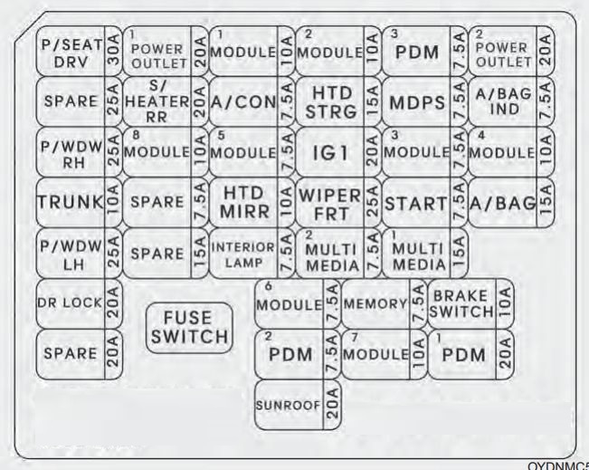
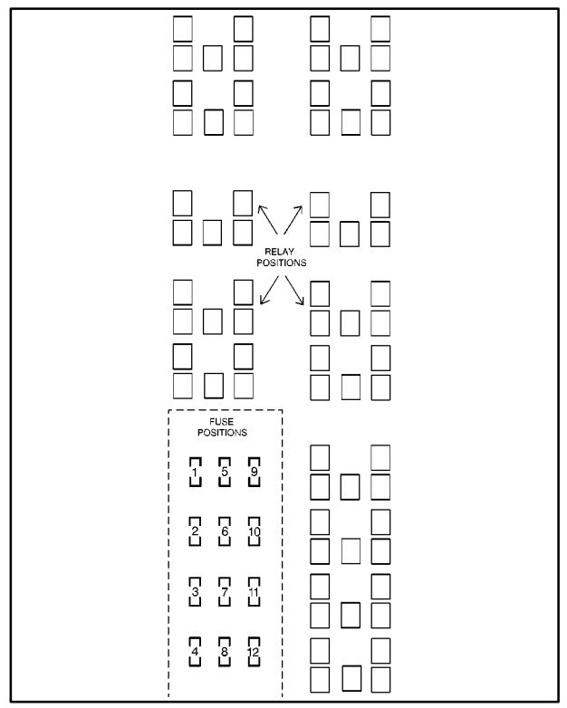
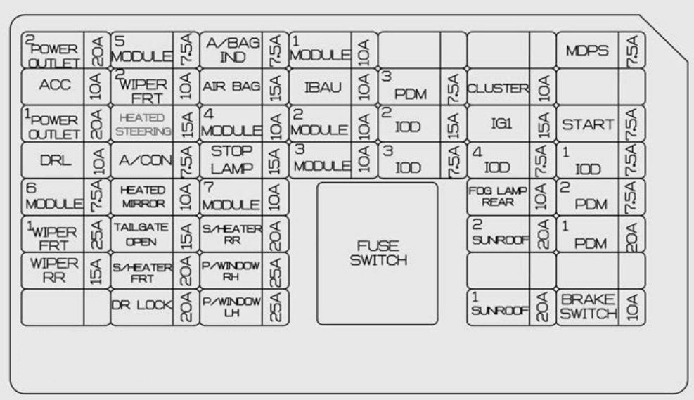
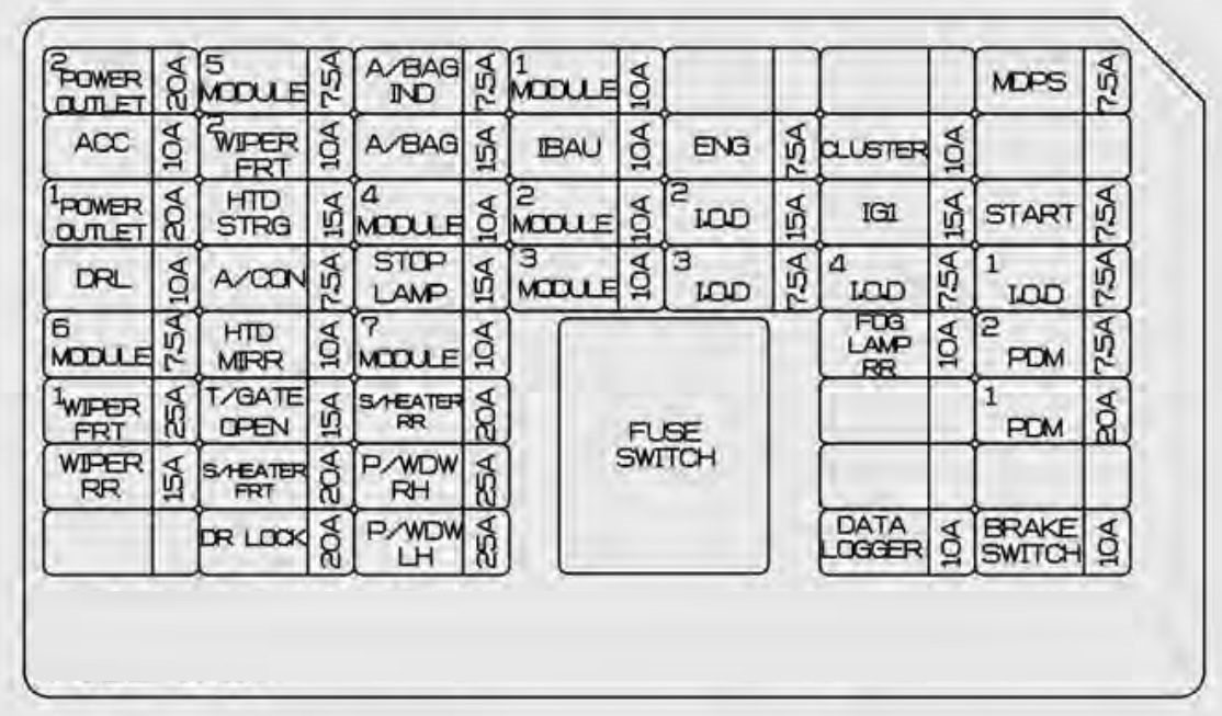
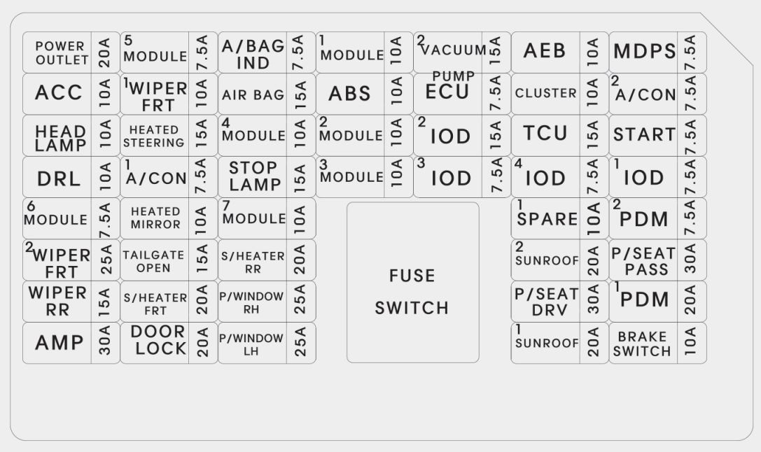
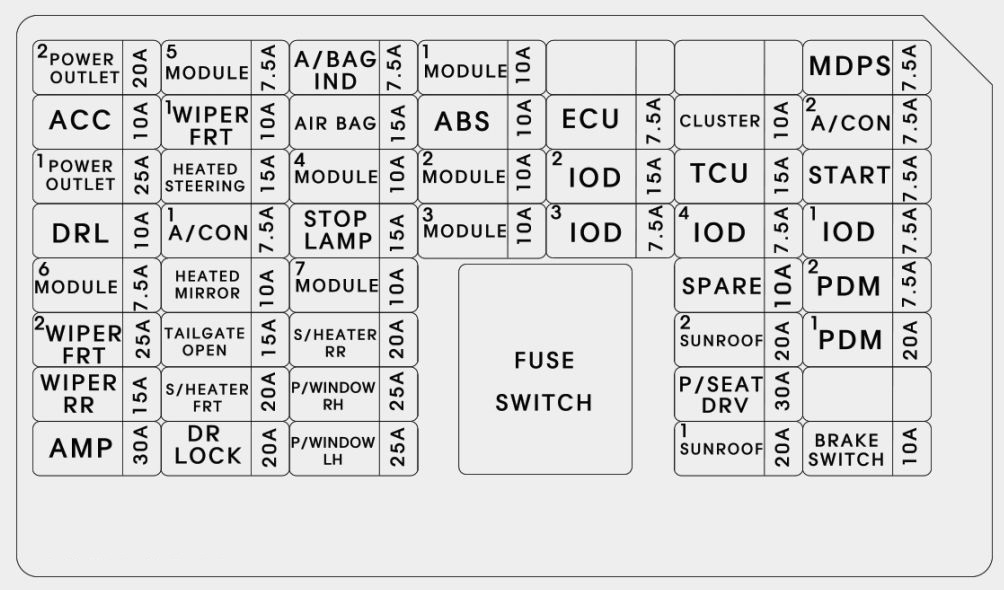
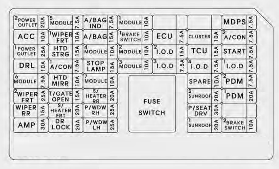
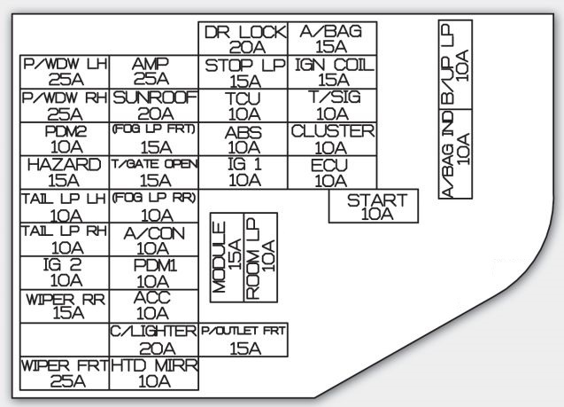
Instrument panel
| Description | Fuse rating | Protected component |
| MODULE 3 | 7,5 | Key Solenoid, Sport Mode Switc |
| PDM 1 | 25 | Smart Key Control Module |
| POWER OUTLET | 15 | Front Power Outlet |
| MODULE 5 | 7,5 | Smart Key Control Module, Rear Seat Warmer Relay LH/RH |
| MODULE 2 | 7,5 | BCM, Panorama Sunroof, Rain Sensor |
| TRUNK | 10 | I/P Junction Box (Trunk Relay), Fuel Filler Door & Trunk Lid Switch, Trunk Room LP |
| CLOCK | 10 | A/V & Navigation Head Unit, Audio, Smart Key Control Module, Overhead Console Lamp, Crash Pad Mood Lamp, A/C Control Module, BCM, AMP, Power Outside Mirror Switch, Driver/Passenger Door Mood Lamp |
| C/LIGHTER | 15 | Cigar Lighter |
| HTD STRG | 15 | Steering Wheel Heater |
| A/CON | 7,5 | A/C Control Module, E/R Fuse & Relay Box (Blower Relay) |
| WIPER | 25 | Multifunction Switch, Front Wiper Motor, E/R Fuse & Relay Box (Wiper Relay, Rain SNSR Relay) |
| S/HEATER FRT | 20 | Driver/Passenger CCS Cushion Warmer, Driver/Passenger Seat Warmer Module |
| MIRR HTD | 10 | Driver/Passenger Power Outside Mirror |
| MODULE 4 | 7,5 | Front Seat Warmer & CCS Switch, Driver/Passenger CCS Control Module, Driver/Passenger Seat Warmer Module, Tire Pressure Monitoring Module, Audio |
| A/BAG IND | 7,5 | Instrument Cluster (Air Bag IND.) |
| START | 7,5 | W/O Smart Key : Burglar Alarm Relay With Smart Key : PCM, Transaxle Range Switch |
| S/HEATER RR | 15 | Rear Seat Warmer Relay LH/RH |
| P/SEAT PASS | 20 | Passenger Seat Manual Switch |
| FOG LP RR | 15 | — |
| MODULE 1 | 7,5 | Head Lamp Leveling Device Actuator LH/RH, Auto Head Lamp Leveling Device Module, Driver IMS Module, ATM Lever Indicator, BCM, A/C Control Module, Electro Chromic Mirror, Lane Keeping Assist Module, Instrument Cluster |
| VACCUM | 20 | Vacuum Pump, Vacuum Switch |
| A/BAG | 15 | Telltale Lamp, SRS Control Module, Passenger Weight Classification Sensor |
| P/WDW LH | 25 | I/P Junction Box (Power Window LH Relay), Driver/Passenger Power Window Safety Module |
| AMP | 30 | AMP |
| PDM 2 | 7,5 | Start Stop Button Switch, Smart Key Control Module, Fob Holder |
| MDPS | 10 | EPS Control Module, Crash Pad Switch |
| PDM 3 | 7,5 | Smart Key Control Module |
| P/WDW RH | 25 | I/P Junction Box (Power Window RH Relay) |
| P/SEAT DRV | 30 | Driver IMS Module, Driver Seat Manual Switch, Driver Lumbar Support Switch |
| DR LOCK | 20 | Two Turn Unlock Relay, I/P Junction Box (Door Lock Relay, Door Unlock Relay, Turn Signal Lamp Sound Relay |
| SUNROOF | 20 | Panorama Sunroof |
| IG 1 | 20 | E/R Fuse & Relay Box (Fuse : ABS 3 10A, TCU 2 15A, ECU 4 10A) |
| POWERCONNECTOR | 15 – AUDIO | A/V & Navigation Head Unit, Audio |
| 10 – ROOM LP | Driver/Passenger Smart Key Outside Handle, Driver IMS Module, Lamp Auto Cut Relay, Driver/Passenger Door Scuff Lamp, Ignition Key ILL. & Door Warning Switch, A/C Control Module, Data Link Connector, RF Receiver, BCM, Electro Chromic Mirror, Instrument Cluster, Auto Light & Photo Sensor, Tire Pressure Monitoring Module |
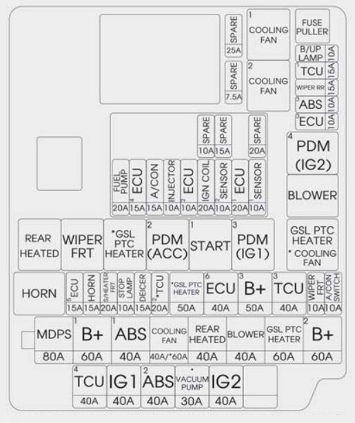
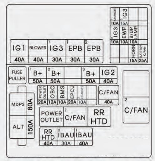
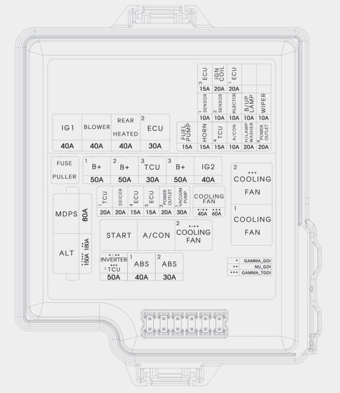
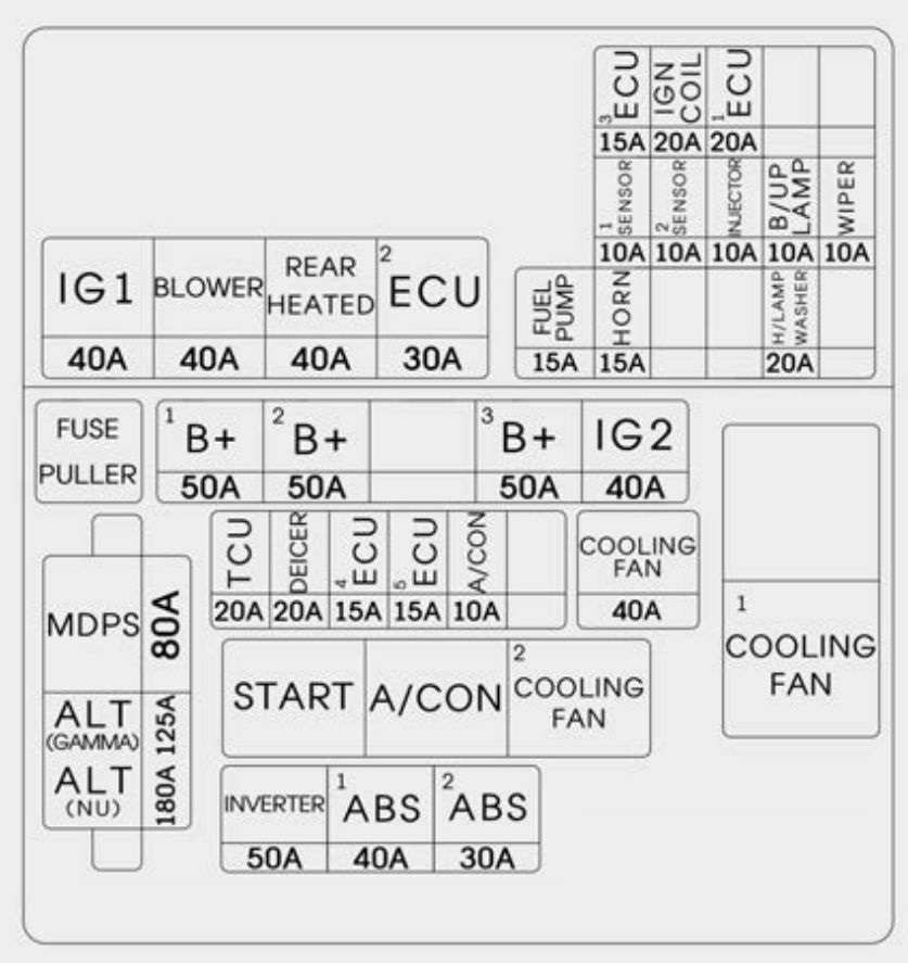
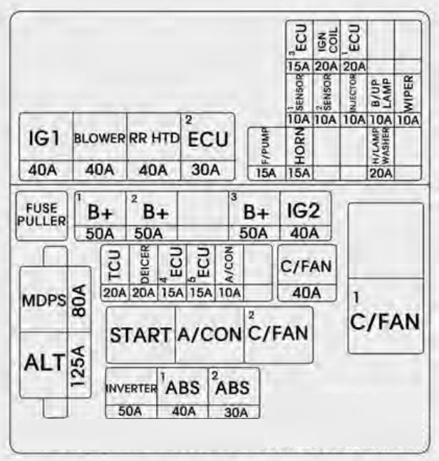
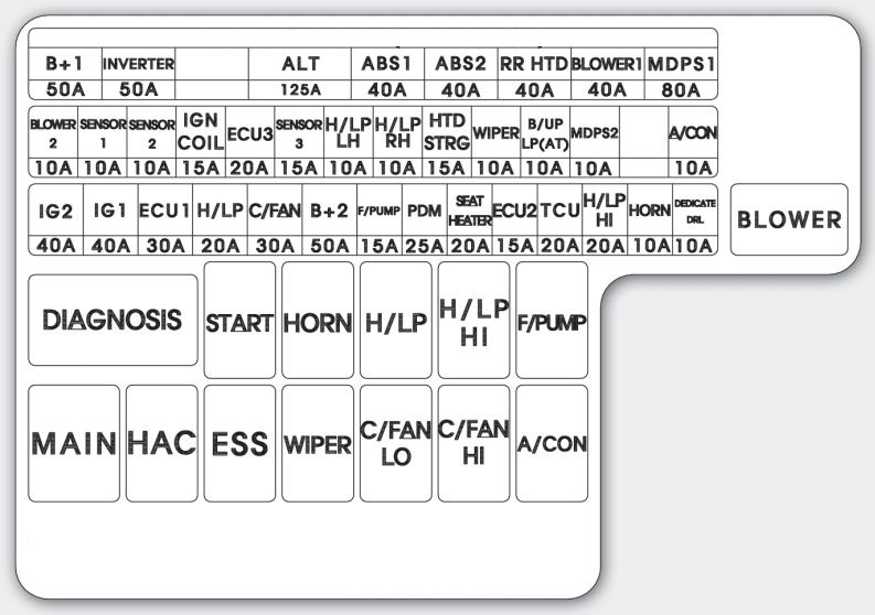
Engine compartment
| Fuse name | Fuse rating [A] | Protected component | |
| MULTI FUSE | IP B+ 2 | 50 | I/P Junction Box (P/SEAT DRV 30A, P/SEAT PASS 20A, AMP 30A, PDM 2 7.5A, IPS 5, IPS 6, ARISU 2) |
| B+ 4 | 60 | — | |
| IGN 2 | 40 | E/R Fuse & Relay Box (Start Relay), Fuse & Relay Box (PDM 3(IG 2) Relay), Ignition Switch | |
| ABS 1 | 40 | ESC Module | |
| RR HTD (G4KJ)/ | 40 | E/R Fuse & Relay Box (RR HTD Relay) (G4KJ) | |
| C/FAN HI (G4KH) | 60 | C/FAN (HI) Relay (G4KH) | |
| BLOWER | 40 | E/R Fuse & Relay Box (Blower Relay) | |
| IP B+ 1 | 60 | I/P Junction Box (PDM 1 25A, MODULE 3 7.5A, S/HEATER FRT 20A, S/HEATER RR 15A TRUNK 10A, P/WDW LH 25A, P/WDW RH 25A), Power Connector (AUDIO 15A)) | |
| MDPS | 80 | EPS Control Module | |
| FUSE | WIPER | 10 | PCM |
| RR HTD IND | 10 | A/C Control Module | |
| AMS | 10 | A/C Control Module | |
| AMS | 10 | Battery Sensor | |
| TCU 1 | 10 | PCM | |
| STOP LP | 10 | E/R Fuse & Relay Box (HAC Relay), Smart Key Control Module, Stop Lamp Switch | |
| DEICER | 10 | E/R Fuse & Relay Box (Deicer Relay) | |
| H/LP WASHER | 10 | — | |
| LDC 1 | 30 | — | |
| C/FAN | 40 | E/R Fuse & Relay Box (C/Fan(HI) Relay, C/Fan(LO) Relay) | |
| ABS 2 | 30 | Multipurpose Check Connector, ESC Module | |
| LDC 2 | 30 | — | |
| CVVL | 40 | — | |
| RR THD (G4KH) | RR HTD Relay (G4KH) | ||
| IP B+ 3 | 50 | I/P Junction Box (Power Connector (ROOM LP 10A), SUNROOF 20A, DR LOCK 20A IPS 1, IPS 3, ARISU 1) | |
| IGN 1 | 40 | Fuse & Relay Box (PDM 1(ACC) Relay, PDM 2(IG 1) Relay), Ignition Switch | |
| EMS | 40 | EMS Box (HORN 15A, ECU 3 10A, ECU 1 30A, F/PUMP 20A) | |
| ECU 4 | 10 | PCM | |
| TCU 2 | 15 | Back-Up Lamp Switch, Vehicle Speed Sensor, Transaxle Range Switch | |
| ABS 3 | 10 | E/R Fuse & Relay Box (HAC Relay), Stop Lamp Switch, ESC Module, Multipurpose Check Connector | |
| B/UP LP | 10 | A/V & Navigation Head Unit, Audio, Electro Chromic Mirror, BCM, Rear Combination Lamp(In) LH/RH | |
| A/CON | 10 | A/C Control Module | |
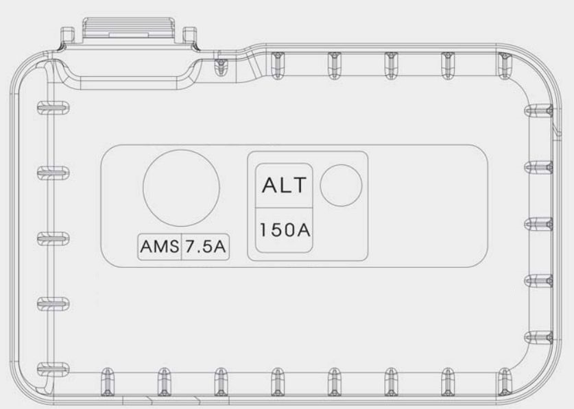
Engine compartment fuse panel (EMS BOX)
| Fuse Name | Fuse rating | Protected component |
| HORN | 15 | EMS Box (Horn Relay), E/R Fuse & Relay Box (B/Horn Relay) |
| F/PUMP | 20 | EMS Box (F/Pump Relay) |
| ECU 3 | 15 | PCM |
| SNSR 1 | 15 | Oxygen Sensor (Up/Down), E/R Fuse & Relay Box (C/FAN (HI/LO) Relay) |
| INJECTOR | 10 | EMS Box (F/Pump Relay) |
| SNSR 3 | 10 | Camshaft Position Sensor #1, #2, Immobilizer Module |
| SNSR 2 | 10 | RCV Control Solenoid Valve(G4KH), Variable Intake Solenoid Valve(G4KJ), Canister Close Valve Oil Control Valve #1, #2, Purge Control Solenoid Valve, Crankshaft Position Sensor |
| IGN COIL | 20 | Condenser, Ignition Coil #1, #2, #3, #4 |
| ECU 1 | 30 | EMS Box (Engine Control Relay) |
WARNING: Terminal and harness assignments for individual connectors will vary depending on vehicle equipment level, model, and market