KIA Rondo (2017) – fuse box diagram
Year of production: 2017
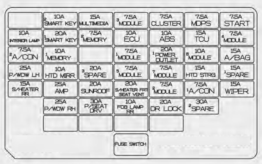
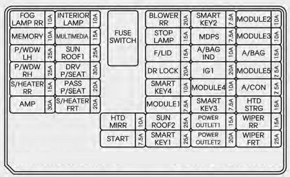
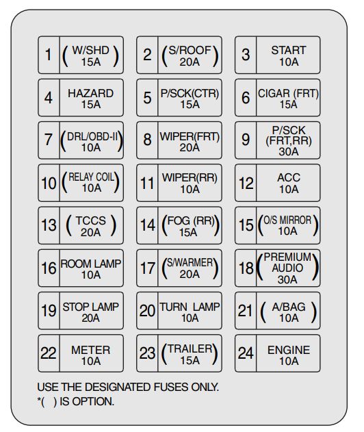
Instrument panel (Driver’s side fuse panel)
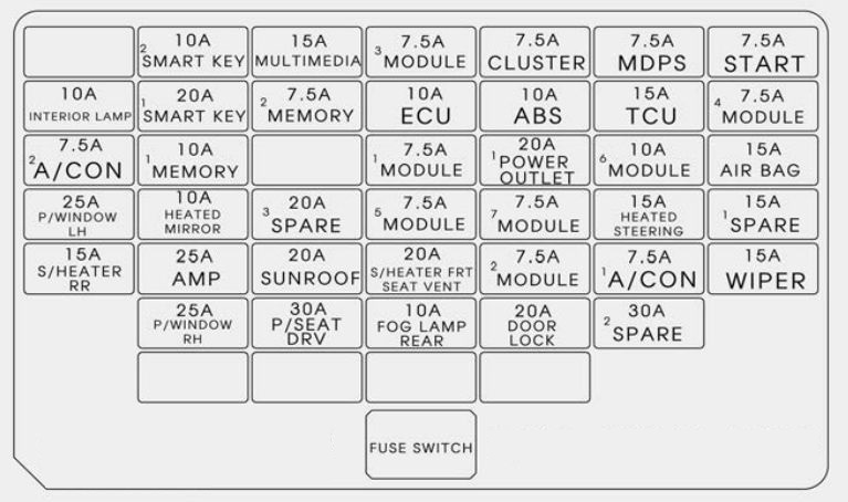
| Number | Ampere rating [A] | Description | Protected component |
| 1 | 10 | PDM 2 | Start/Stop Button Switch, Immobilizer Module |
| 2 | 15 | MULTI MEDIA | DC-DC Converter (Audio), A/V & Navigation Head Unit, Audio |
| 3 | 7,5 | MODULE 3 | Seat Warmer Control Module, Rear Seat Warmer Module, Passenger Seat Warmer Module, DC-DC Converter (AMP), Auto Head Lamp Leveling Device Module, Rain Sensor, Head Lamp Leveling Device Actuator LH/RH, A/C Control Module, Electro Chromic Mirror, Head Lamp Leveling Device Switch, A/V Navigation Head Unit |
| 4 | 7,5 | CLUSTER | Instrument Cluster, DC-DC Converter (Audio) |
| 5 | 7,5 | MDPS | MDPS Unit |
| 6 | 7,5 | START | ICM Relay Box (B/Alarm Relay), Ignition Lock Switch. [A/T – Transaxle Range Switch], [M/T – E/R Junction Block, (RLY. 10), ECM/PCM, Smart Key Control Module] |
| 7 | 10 | INTERIOR LAMP |
Driver/Passenger Power Outside Mirror, Driver/Passenger Foot Lamp, Ignition Key ILL. & Door Warning Switch, Overhead Console Lamp, Room Lamp, Vanity Lamp LH/RH, Rear Personal Lamp LH/RH, Luggage Lamp, Portable Lamp |
| 8 | 20 | PDM | Smart Key Control Module |
| 9 | 7,5 | MEMORY 2 | RF Receiver |
| 10 | 10 | ECU | Smart Key Control Module, Immobilizer Module, Vehicle Speed Sensor, ECM/PCM, Air Flow Sensor (D4FD), Glow Relay Un |
| 11 | 10 | ABS | ABS/ESC Control Module |
| 12 | 15 | TCU | TCM (D4FD), Transaxle Range Switch (A/T, DCT), E/R Junction Block (Fuse – F27) (M/T) |
| 13 | 7,5 | MODULE 4 | BCM |
| 14 | 7,5 | A/CON SW | A/C Control Module |
| 15 | 10 | MEMORY 1 | Instrument Cluster, Auto Light & Photo Sensor, Tire Pressure Monitoring Module, Ultrasonic Instrusion Protection Sensor, A/C Control Module, Data Link Connector, Siren Control Module, Clock, BCM |
| 16 | 7,5 | MODULE 1 | Smart Parking Assist Control Module, Stop Lamp Switch, Tire Pressure Monitoring Module, Clutch Sensor (M/T), Front Parking Assist Sensor (Center)/(Side) LH/RH, Front Parking Assist Sensor (In)/(Out) LH/RH, Rear Parking Assist Sensor Center LH/RH, Crash Pad Switch, Rear Parking Assist Sensor (In)/(Out) LH/RH, Sport Mode Switch, Parking Assist Buzzer, Multipurpose Check Connector, Electric Parking Brake Module, Lane Departure Warning Module, Blind Spot Detection Radar LH/RH |
| 17 | 20 | POWER OUTLET 1 |
Rear Power Outlet, Cigarette Lighter, Front Power Outle |
| 18 | 10 | MODULE 6 | A/V & Navigation Head Unit, DC-DC Converter (Audio/AMP), Audio, Clock, Smart Key Control Module, BCM, E/R Junction Block (RLY. 7), AMP, Power Outside Mirror Switch |
| 19 | 15 | A/BAG | SBR Control Module, Seat Belt Reminder IND.,Instrument Cluster Door Lock & PAB On/Off IND., SRS Control Module, A/C Control Module |
| 20 | 25 | P/WDW LH | Rear Safety Power Window Module LH, Driver/Passenger Safety Power Window Module, Power Window LH Relay |
| 21 | 10 | HTD MIRR | A/C Control Module, ECM/PCM, Driver/Passenger Power Outside Mirror |
| 22 | 7,5 | MODULE 5 | Portable Lamp, Rear Seat Warmer Module, Panorama Sunroof Assembly, Driver/Passenger CCS Control Module, Seat Warmer Control Module, Passenger Seat Warmer Module, E/R Junction Block (RLY. 8) |
| 23 | 7,5 | MODULE 7 | BCM, Smart Key Control Module |
| 24 | 15 | HTD STRG | Steering Wheel Heater |
| 25 | 15 | S/HEATER RR | Rear Seat Warmer Module |
| 26 | 25 | AMP | DC-DC Converter (AMP), AMP |
| 27 | 20 | SUNROOF | Panorama Sunroof Assembly |
| 28 | 20 | S/HEATER FRT |
Driver/Passenger CCS Control Module, Seat Warmer Control Module, Passenger Seat Warmer Module |
| 29 | 7,5 | MODULE 2 | ICM Relay Box (Turn Signal Lamp Sound Relay, Folding/Unfolding Relay), Key Solenoid, Sport Mode Switch, Console Switch LH/RH, Rear Power Window Switch LH/RH |
| 30 | 7,5 | A/CON | Diesel Block (RLY. 2, RLY. 3), E/R Junction Block (RLY. 2), A/C Control Module, Cluster Ionizer |
| 31 | 15 | WIPER | Rear Wiper Motor, ICM Relay Box (Rear Wiper Relay), Multifunction Switch |
| 32 | 25 | P/WDW RH | Rear Safety Power Window Module RH, Driver/Passenger Safety Power Window Module, Power Window RH Relay |
| 33 | 30 | P/SEAT DRV | Driver Seat Manual Switch |
| 34 | 10 | FOG LAMP RR |
ICM Relay Box (Rear Fog Lamp Relay |
| 35 | 20 | DR LOCK | Tail Gate Open Relay, Door Lock/Unlock Relay, ICM Relay Box (Dead Lock Relay) |
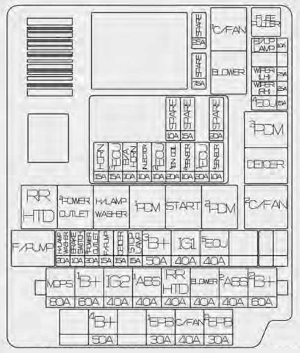
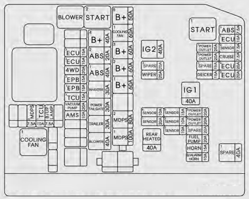
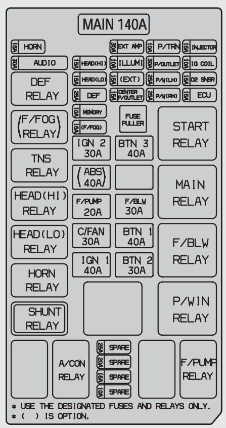
Engine compartment main fuse panel
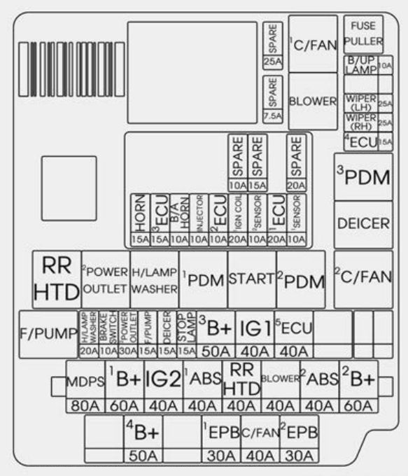
| Fuse | Ampere rating [A] | Description | Protected component |
| MULTI FUSE | 80 | MDPS | MDPS Unit |
| 60 | B+1 | Smart Junction Block (IPS 1, IPS 2, IPS 3, IPS 4, Fuse – F2/F9/F22/F29/F36) | |
| 40 | IG2 | RLY. 10 (Start Relay), Ignition Switch (W/O Button Start), RLY. 3 (PDM 3 (IG2) Relay, With Button Start) | |
| 40 | ABS 1 | ABS/ESC Control Module | |
| 40 | RR HTD | RLY. 6 (Rear Defogger Relay) | |
| 40 | BLOWER | RLY. 2 (Blower Relay) | |
| 40 | ABS 2 | ABS/ESC Control Module, Multipurpose Check Connector | |
| 60 | B+2 | Smart Junction Block (IPS 5, IPS 6, IPS 7, IPS 8, Fuse – F31/F37/F38) | |
| FUSE | 50 | B+4 | E/R Junction Block (Fuse – F29/F30/F31) |
| 30 | EPB 1 | Electric Parking Brake Module | |
| 50 | C/FAN | RLY. 1 (C/Fan 1 Relay), RLY. 5 (C/Fan 2 Relay) | |
| 30 | EPB 2 | Electric Parking Brake Module | |
| 20 | H/LP WASHER | RLY. 8 (Head Lamp Washer Relay) | |
| 10 | BRAKE SWITCH | Stop Lamp Switch, Smart Key Control Module | |
| 30 | POWER OUTLET 2 | RLY. 7 (Power Outlet Relay) | |
| 15 | FUEL PUMP | RLY. 12 (Fuel Pump Relay) | |
| 15 | DEICER | RLY. 4 (Deicer Relay) | |
| 15 | STOP LAMP | Stop Signal Electronic Module | |
| 50 | B+3 | Smart Junction Block (Leak Current Autocut Device, Fuse – F30/F32/F33/F39) | |
| 40 | IG1 | RLY. 9 (PDM 1 (ACC) Relay), RLY. 11 (PDM 2 (IG 1) Relay), Ignition Switch | |
| 40 | ECU 5 | EMS Block (Fuse – F32/F33/F34, Engine Control Relay) | |
| 10 | B/UP LP | MT – Back-Up Lamp Switch | |
| A/T – Rear Combination Lamp (In) LH/RH, Electro Chromic Mirror, A/V & Navigation Head Unit, Audio, Instrument Cluster |
|||
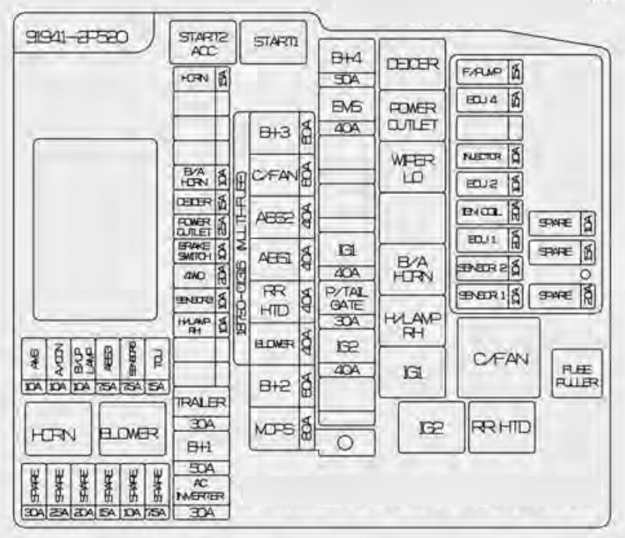
| 25 | WIPER (LH) | Front Wiper Motor LH | |
| 25 | WIPER (RH | Front Wiper Motor RH | |
| 15 | ECU 4 | ECM/PCM | |
| 15 | HORN | Horn Relay | |
| 15 | ECU 3 | PCM (A/T), ECM (M/T) | |
| 10 | B/ALARM | B/Alarm Horn Relay, Horn Relay | |
| 10 | INJECTOR | G4NA : Injector #1/#2/#3/#4 | |
| 10 | ECU 2 | G4FD : PCM (A/T), ECM (M/T) | |
| G4NC : PCM (A/T), ECM (M/T) | |||
| 20 | IGN COIL 1 | Ignition Coil #1/#2/#3/#4, Condenser | |
| 10 | SENSOR 2 | G4FD : Oil Control Valve #1/ #2, Oil Level Sensor, E/R Junction Block (RLY. 1, RLY. 5) | |
| G4NA/G4NC : Oil Control Valve #1/ #2, Camshaft Position Sensor (Intake/Exhaust), Oil Level Sensor (G4NC), E/R Junction Block (RLY. 1, RLY. 5) | |||
| 20 | ECU 1 | PCM (A/T), ECM (M/T) | |
| 10 | SENSOR 1 | Oxygen Sensor (Up/Down), Variable Intake Solenoid Valve, Purge Control Solenoid Valve |
| Relay name | Type |
| C/FAN 1 RELAY | Plug Micro |
| BLOWER RELAY | Plug Micro |
| PDM3 (IG2) Relay | Plug Micro |
| Deicer Relay | Plug Micro |
| C/Fan 2 Relay | Plug Micro |
| RR HTD Relay | Plug Micro |
| Power Outlet Relay | Plug Micro |
| H/Lamp Washer Relay | Plug Micro |
| PDM1 (ACC) RELAY | Plug Micro |
| START RELAY | Plug Micro |
| PDM2 (IG1) Relay | Plug Micro |
| Fuel Pump Relay | Plug Micro |
| Engine Control Relay | PCB |
| B/Alarm Horn Relay | PCB |
| Horn Relay | PCB |
WARNING: Terminal and harness assignments for individual connectors will vary depending on vehicle equipment level, model, and market