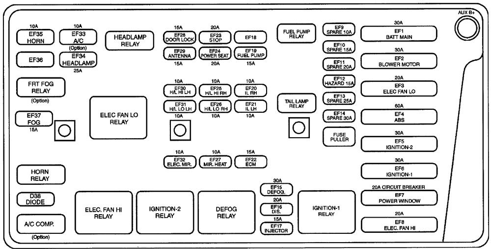
| Fuse number |
Ampere rating [A] |
Source |
Circuit protected |
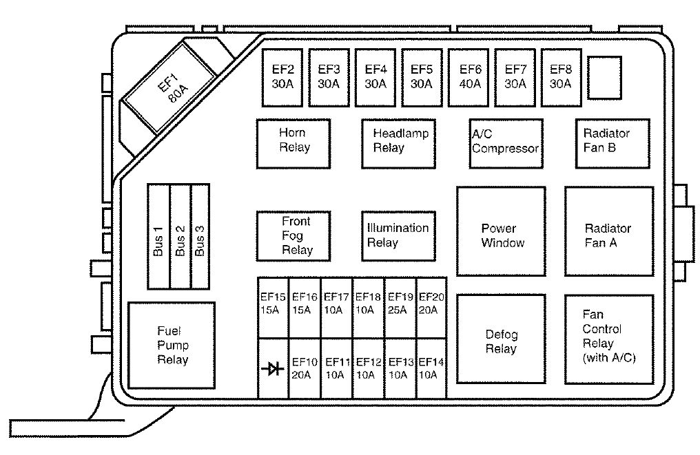
| EF1 (Engine Fuse) |
30 |
B+ |
Fuses F1 , F2, F4 |
| EF2 |
30 |
B+ |
Blower Motor Relay, Blower Motor, Auto. Temp. Control Relay, ATC Controller |
| EF3 |
20 |
B+ |
Cooling Fan (Low) Relay, Aux. Cooling Fan, Cooling Fan Control Relay |
| EF4 |
60 |
B+ |
ABS Relay, Electronic Brake Control Module |
| EF5 |
30 |
B+ |
lgn 2 (lgn Key}, Starter |
| EF6 |
30 |
B+ |
lgn 1 (lgn Key), Ace, F17, F18 |
| EF7 |
20 |
B+ |
lgn 2 Relay, EF 32, Keyless Entry System, Sun Roof, Power Window Main Switch |
| EF8 |
20 |
B+ |
Cooling Fan (High) Relay, Cooling Fan Control Relay, Main Cooling Fan |
| EF12 |
15 |
B+ |
Hazard Switch |
| EF15 |
30 |
B+ |
Rear Window Defogger, Defogger Relay, EF27 |
| EF16 |
20 |
B+ |
Generator Terminal F, Electronic Ignition System Coil, Evaporativer Emission Canister Purge Solenoid, Engine Control Module |
| EF17 |
15 |
B+ |
Fuel Injectors, EGA |
| EF19 |
15 |
B+ |
Fuel Pump, DLC Connector E |
| EF20 |
10 |
B+ |
RH Parking Lamp, RH Taillamp, Dimmer Control Switch, Chime bell |
| EF21 |
10 |
B+ |
LH Parking Lamp, LH Taillamp, License Lamp |
| EF22 |
15 |
B+ |
Engine Control Module |
| EF23 |
20 |
B+ |
Brake Switch, Brake Lamps, EBCM, Cruise Control, BTSi |
| EF24 |
20 |
B+ |
Power Seat |
| EF25 |
10 |
EF34 |
Headlamp High RH |
| EF26 |
10 |
EF34 |
Headlamp Low RH |
| EF27 |
10 |
EF15 |
Electric Outside Rearview Mirror Defogger |
| EF28 |
15 |
B+ |
Auto Door Lock System |
| EF29 |
15 |
B+ |
Power Antenna, lgn Key Illumination, Luggage Compartment Lamp, Interior Courtesy Lamp, Door Step Lamp, Keyless Entry System Unit |
| EF30 |
10 |
EF34 |
Headlamp High LH |
| EF31 |
10 |
EF34 |
Headlamp Low LH |
| EF32 |
10 |
EF7 |
Electric Outside Rearview Mirror Control, Map Lamp (W/0 Sun Roof), Sun Roof Switch, Keyless Entry Unit |
| EF33 |
10 |
B+ |
NC Compressor Relay, NC Compressor, NC Diode |
| EF34 |
25 |
B+ |
Headlamp Relay, EF30, EF25, EF31 , EF26, High Beam Indicator Switch, Illumination Relay, Headlamp Switch, Anti-Theft Siren |
| EF35 |
10 |
B+ |
Horn System |
| EF37 |
15 |
B+ |
Fog Lamp Relay, LH and RH Front Fog Lamps |
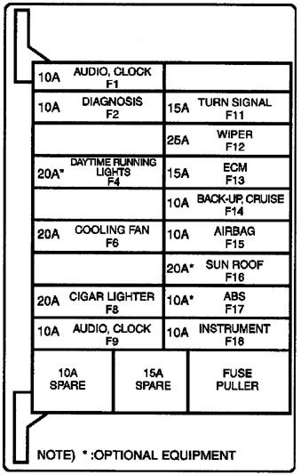
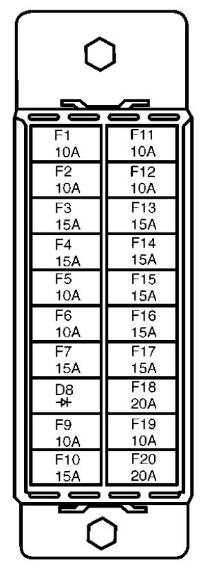
| F1 (Fuse) |
10 |
EF1 |
Audio System, Clock, Key Remind Switch, Chime Module, Ashtray Ilium., Door Switch, ATC Controller |
| F2 |
10 |
EF1 |
DLC |
| F4 |
20 |
EF1 |
Daytime Running Lamps |
| F6 |
20 |
EF5 (Ign 2) |
lgn 2 Relay, Cooling Fan (High) Relay, Cooling Fan (Low) Relay, A/C Compressor Relay, A/C Switch, Cooling Fan Control Relay, ECM., Blower Motor Relay, Auto. Temp. Control Relay, Defogger Relay, ATC Controller |
| F8 |
20 |
EF6 (Acc) |
Cigar Lighter, Glove Box Lamp, Glove Box Switch, Key Interlock Solenoid |
| F9 |
10 |
EF6 (Acc) |
Audio System, Clock |
| F11 |
15 |
EF6 (Ign 1) |
Turn Signal/Hazard Switch, Daytime Running Lamps |
| F12 |
25 |
EF6 (Ign 1) |
Wiper/Washer System |
| F13 |
15 |
EF6 (Ign 1) |
Engine Control Module, lgn 1 Relay, Vehicle Speed Sensor, Fuel Pump Relay, CMP |
| F14 |
10 |
EF6 (Ign 1) |
Backup Switch, Backup Lamps, Defogger, ATC Controller, Seat Belt Switch, Cruise Control Systell’ |
| F15 |
10 |
EF6 (Ign 1) |
Supplemental Inflatable Restraint System |
| F16 |
20 |
EF6 (Ign 1) |
Sun Roof Module, Sun Roof Motor (if equipped) |
| F17 |
10 |
EF6 (Ign 1) |
Electronic Brake Control Module |
| F18 |
10 |
EF6 (Ign 1) |
Instrument Cluster, Chime Module, Brake Switch, ATC. Controller, Vehicle Speed Sensor, ECM, Brake Transaxle Shift Interlock Solenoid, Transmission Range Switch, Speed Sensitive Power Steering Module, EBCM |