Chevrolet Sonic (2013 – 2016) – fuse box diagram
Year of production: 2013, 2014, 2015, 2016
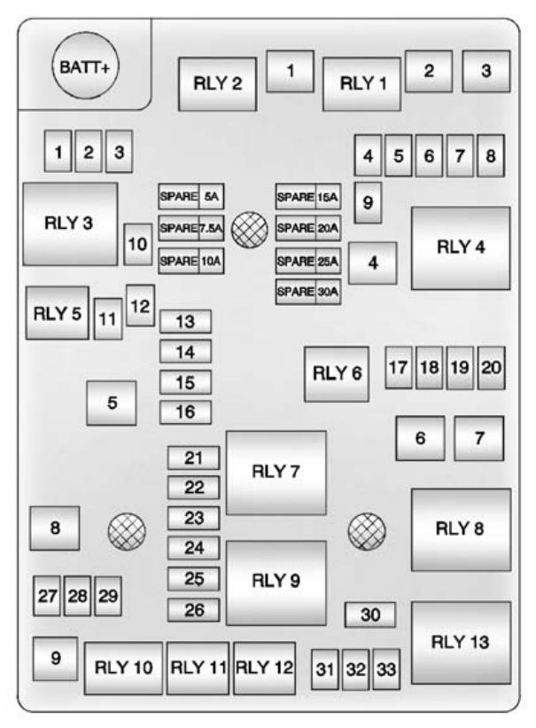
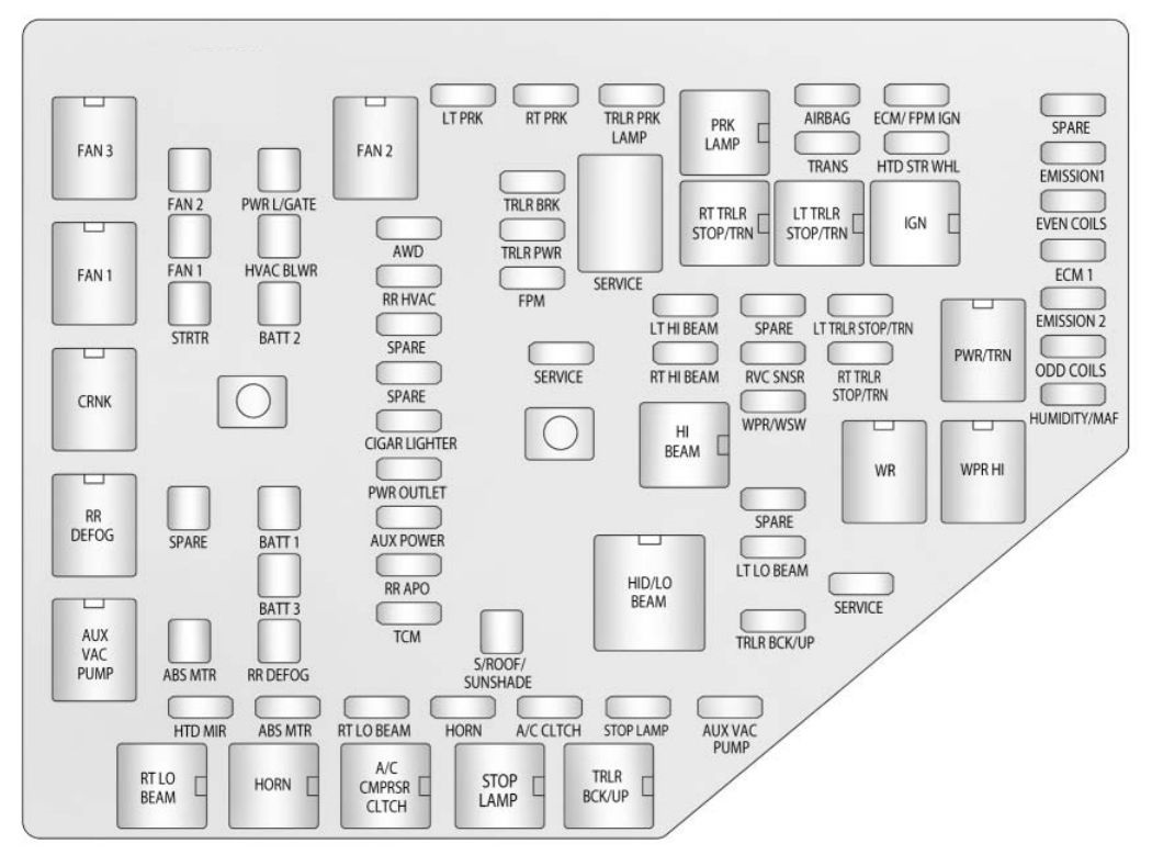
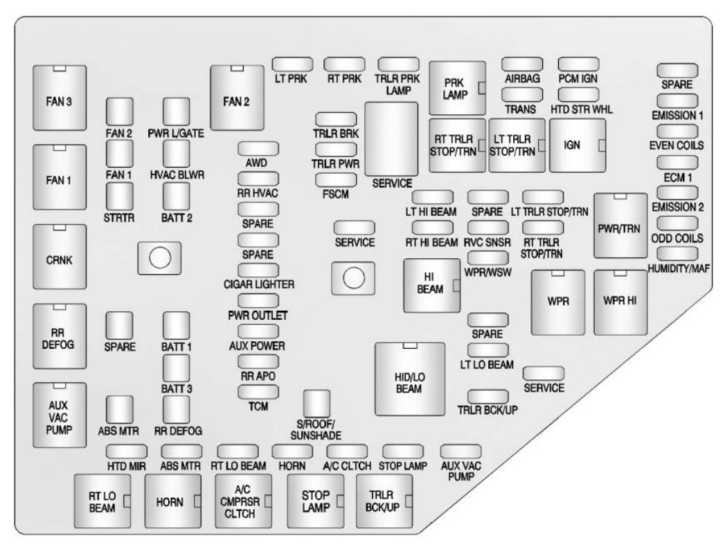
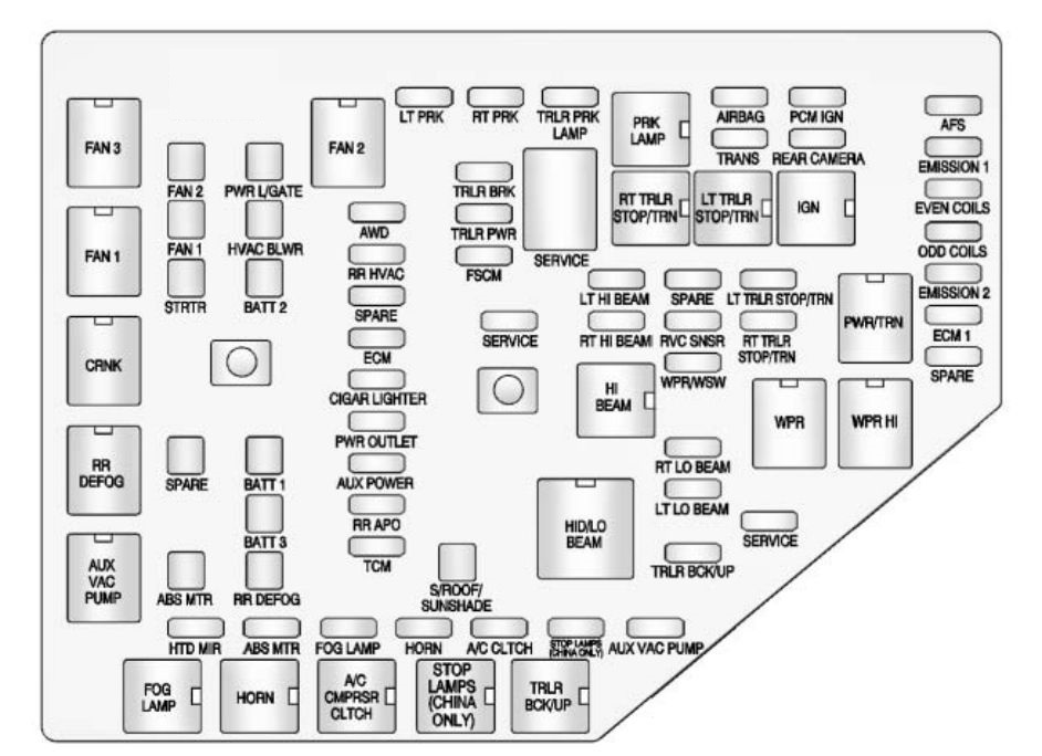
Engine Compartment Fuse Block
The engine compartment fuse block is located on the driver side of the vehicle, near the battery.
LUV and LUW Engines
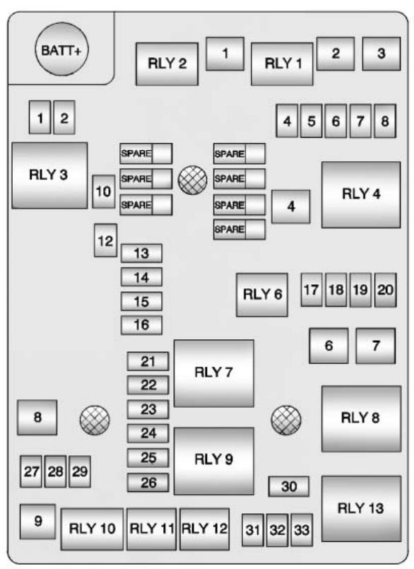
| Mini fuses | Usage |
| 1 | Antilock Brake System Valve |
| 2 | Sunroof |
| 4 | Rear Wiper |
| 5 | Regulated Voltage Control |
| 6 | Antilock Brake System Fluid |
| 7 | Automatic Occupant Sensing/ROS |
| 8 | Outside Rearview Mirror |
| 10 | Rear Window Defogger |
| 12 | Heated Outside Rearview Mirror |
| 13 | Heated Front Seat |
| 14 | Fuel System Control Module 1 |
| 15 | Flex Fuel |
| 16 | Washer |
| 17 | Fuel Pump (1.8L) |
| 18 | Engine Control Module 5 |
| 19 | Fuel System Control Module 2/Leveling |
| 20 | Transmission Control Module 1 |
| 21 | Engine Control Module 1 |
| 22 | Coil |
| 23 | Engine Control Module 4 |
| 24 | Engine Control Module 3 |
| 25 | Engine Control Module 2 |
| 26 | Injector/ Ignition Coil |
| 27 | Engine Control Module |
| 28 | Air Conditioning Compressor Clutch |
| 29 | Transmission Control Module |
| 30 | Horn |
| 31 | Front Fog Lamps |
| 32 | Left High Beam |
| 33 | Right High Beam |
| SPARE | Spare |
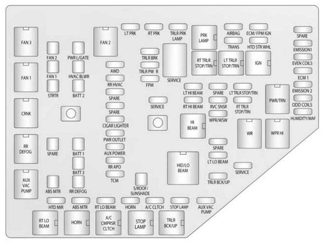
| J-Case fuse | Usage |
| 1 | Antilock Brake System Pump |
| 2 | Front Wiper |
| 3 | Blower |
| 4 | Run/Crank IEC |
| 6 | Cooling Fan K5 |
| 7 | Cooling Fan K4 |
| 8 | EVP |
| 9 | Start |
| Relays | Usage |
| RLY 1 | Front Wiper Control Relay |
| RLY 2 | Front Wiper Speed Relay |
| RLY 3 | Rear Window Defogger Relay |
| RLY 4 | Run/Crank Relay |
| RLY 6 | Fuel Pump Relay (1.8L) |
| RLY 7 | Cooling Fan K2 Relay (1.4L) |
| RLY 8 | Cooling Fan K3 Relay (1.8L), Cooling Fan K3 High Current Relay (1.4L) |
| RLY 9 | Powertrain Relay |
| RLY 10 | Start High Current Relay |
| RLY 11 | Air Conditioning Compressor Clutch Relay |
| RLY 12 | High-Beam Relay |
| RLY 13 | Cooling Fan K1 Relay |
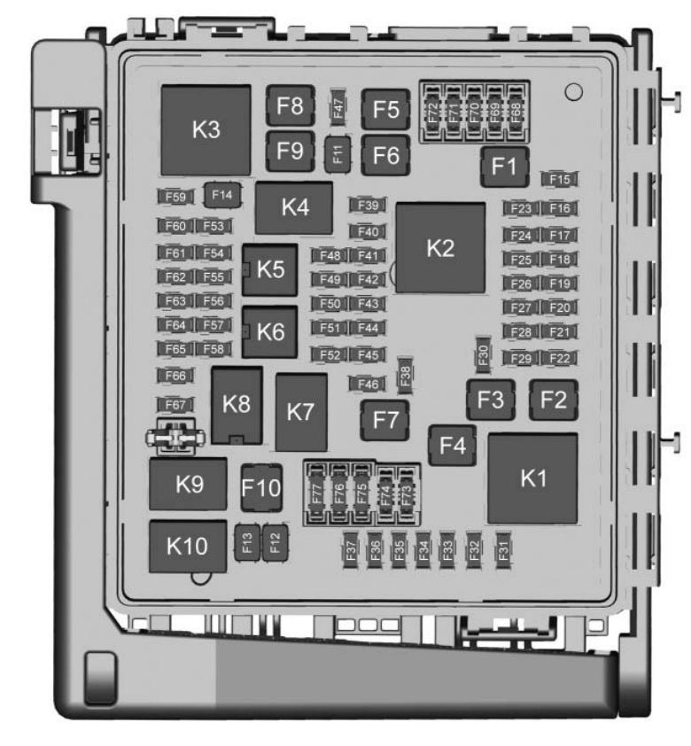
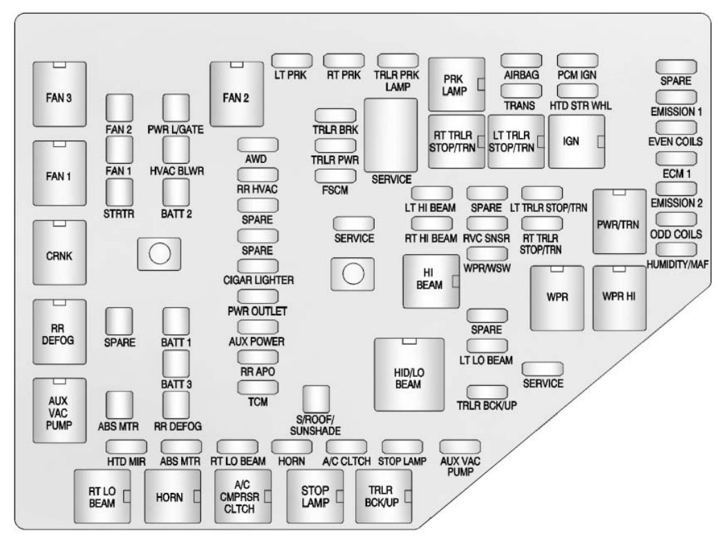
LWE Engine
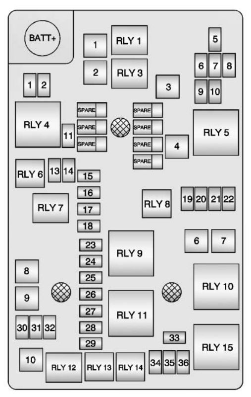
| Mini fuses | Usage |
| 1 | Antilock Brake System Valve |
| 2 | Sunroof |
| 5 | Outside Rearview Mirror |
| 6 | AOS/ROS |
| 7 | ABS Oil |
| 8 | Regulated Voltage Control |
| 9 | Rear Wiper |
| 10 | Not Used/IBS* |
| 11 | Rear Window Defogger |
| 13 | Not Used/SAI Valve* |
| 14 | Heated Outside Rearview Mirror |
| 15 | Heated Seat Front |
| 16 | Fuel System Control Module 1 |
| 17 | Canister Vent |
| 18 | Washer |
| 19 | Fuel Pump* |
| 20 | Engine Control Module 5 |
| 21 | Fuel System Control Module 2/Leveling |
| 22 | Transmission Control Module 1/DC-DC Converter |
| 23 | Auxiliary Water Pump Power |
| 24 | Engine Control Module 1 |
| 25 | Coil |
| 26 | Engine Control Module 4 |
| 27 | Engine Control Module 3 |
| 28 | Engine Control Module 2 |
| 29 | Injector/Ignition Coil |
| 30 | Engine Control Module |
| 31 | Air Conditioning Compressor Clutch |
| 32 | Transmission Control Module |
| 33 | Horn |
| 34 | Front Fog Lamps |
| 35 | Left High Beam |
| 36 | Right High Beam |
| J-Case fuse | Usage |
| 1 | Front Wiper |
| 2 | Antilock Brake System Pump |
| 3 | Blower |
| 4 | Run/Crank IEC |
| 6 | Cooling Fan K5 |
| 7 | Cooling Fan K4 |
| 8 | SAI Pump* |
| 9 | EVP |
| 10 | Start |
| Micro Relays | Usage |
| RLY 1 | Front Wiper Control |
| RLY 3 | Front Wiper Speed |
| HV-Micro Relays | Usage |
| RLY 7 | Auxiliary Water Pump Power* |
| RLY 12 | Start |
| U-Micro Relays | Usage |
| RLY 6 | Not Used/SAI Valve* |
| RLY 8 | Fuel Pump* |
| RLY 13 | Air Conditioning Compressor Clutch |
| RLY 14 | High-Beam Headlamps |
| Mini Relays | Usage |
| RLY 4 | Rear Defogger |
| RLY 5 | Run/Crank |
| RLY 9 | SAI Pump* |
| RLY 10 | Cooling Fan K3 |
| RLY 11 | P/T |
| RLY 15 | Cooling Fan K1 |
* = If equipped
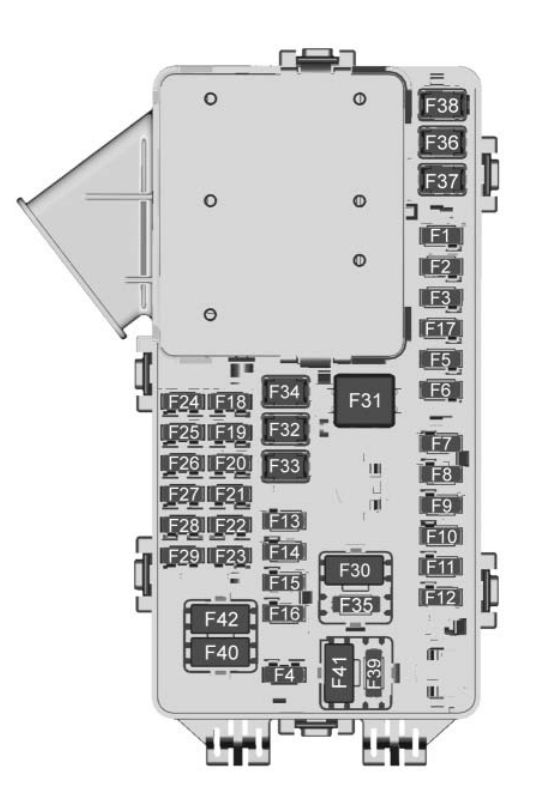
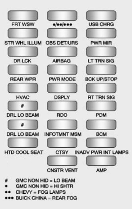
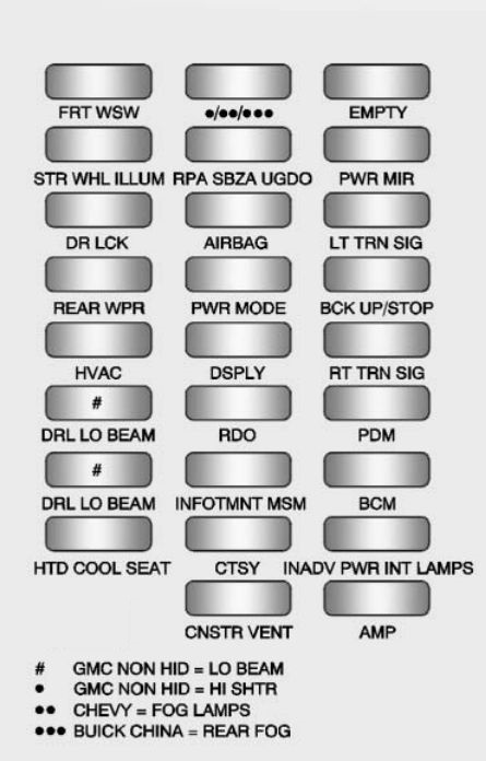
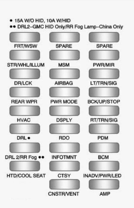
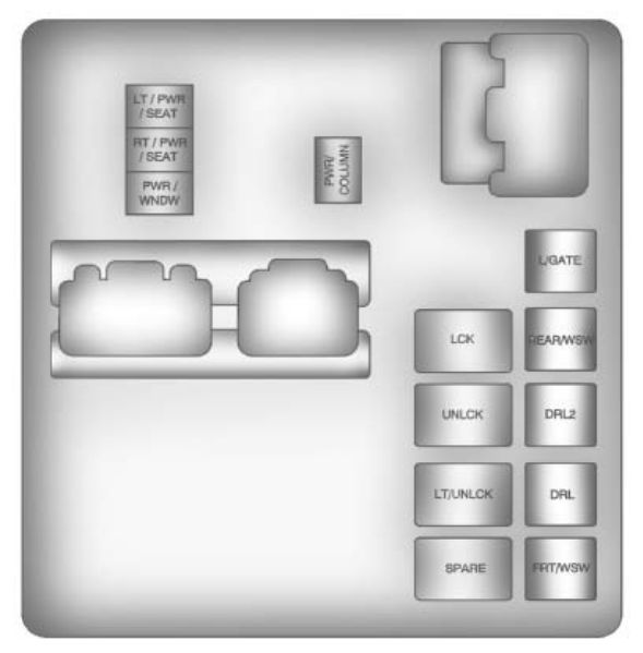
Instrument Panel Fuse Block
The instrument panel fuse block is located on the underside of the driver side instrument panel.
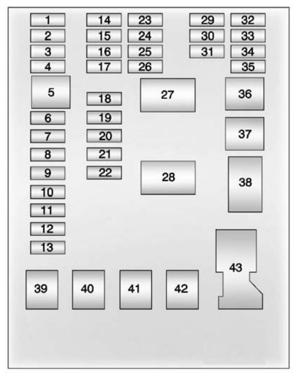
| Fuses | Description |
| 1 | DLIS |
| 2 | Data Link Connector |
| 3 | Airbag |
| 4 | Liftgate |
| 5 | Spare |
| 6 | Body Control Module 8 |
| 7 | Body Control Module 7 |
| 8 | Body Control Module 6 |
| 9 | Body Control Module 5 |
| 10 | Body Control Module 4 |
| 11 | Body Control Module 3 |
| 12 | Body Control Module 2 |
| 13 | Body Control Module 1 |
| 14 | Instrument Cluster |
| 15 | OnStar |
| 16 | Ultrasonic Rear Park Assist |
| 17 | Driver Information Center |
| 18 | Audio |
| 19 | Trailer |
| 20 | VLBS |
| 21 | CHEVYSTAR |
| 22 | Heating, Ventilation, Air Conditioning |
| 23 | HDLP ALC |
| 24 | Clutch |
| 25 | Instrument Panel Cluster/Automatic Occupant Sensing |
| 26 | Airbag Run/Crank |
| 27 | Run Relay |
| 28 | Liftgate Release |
| 29 | Trailer Run/Crank |
| 30 | Clock Spring |
| 31 | Heating, Ventilation, and Air Conditioning |
| 32 | Spare |
| 33 | Sunroof |
| 34 | Cigarette Lighter |
| 35 | Spare |
| 36 | Rear Power Windows |
| 37 | Front Power Windows |
| 38 | RAP/ACCY |
| 39 | DC/DC Converter |
| 40 | Driver Power Window Express Up/Down |
| 41 | PTC2 |
| 42 | PTC1 |
| 43 | Battery Connector |
WARNING: Terminal and harness assignments for individual connectors will vary depending on vehicle equipment level, model, and market.