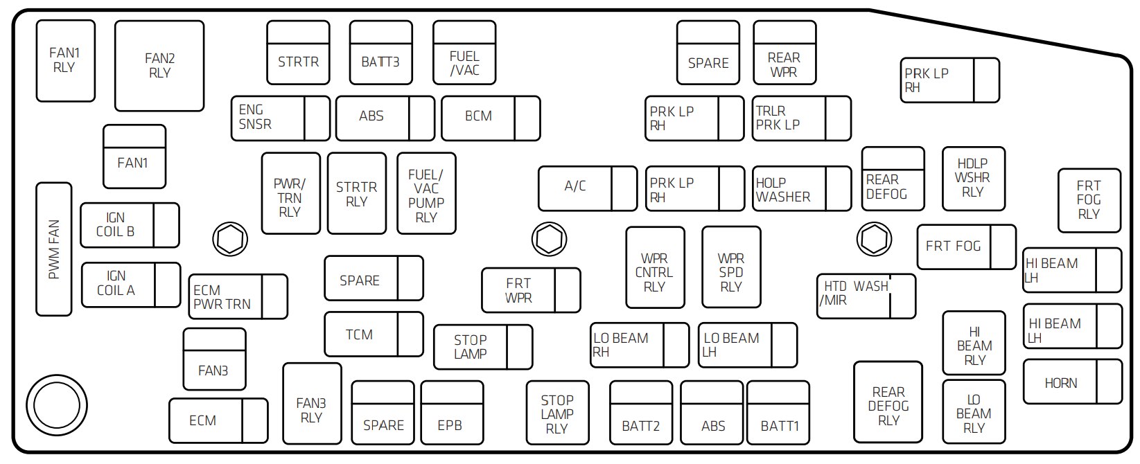
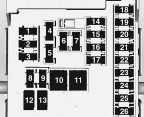
Rechargeable Energy Storage System (High Voltage Battery) Coolant Pump
39
Rechargeable Energy Storage System (High Voltage Battery) Control Module
40
Front Windscreen Washer
41
Right Main-Beam Headlamp
46
—
47
—
49
—
50
Run/Crank – Rear Vision Camera, Accessory Power Module, Tyre Pressure Monitor, Headlamp Levelling Motors (If Equipped)
51
Run/Crank for ABS/Rechargeable Energy Storage System (High Voltage Battery)
52
Engine Control Module/Transmission Control Module – Run/Crank
53
Traction Power Inverter Module – Run/Crank
54
Run/Crank – Fuel System Control Module, Air Conditioning Control Module, On-Board Charger
J-case fuse
Usage
16
—
18
—
19
Power Window – Front
20
—
21
Antilock Brake System Electronic Control Unit
23
Charge Port Door
27
—
28
—
29
—
30
Antilock Brake System Motor
42
Cooling Fan – Right
43
Front Wipers
44
Charger
45
—
48
Cooling Fan – Left
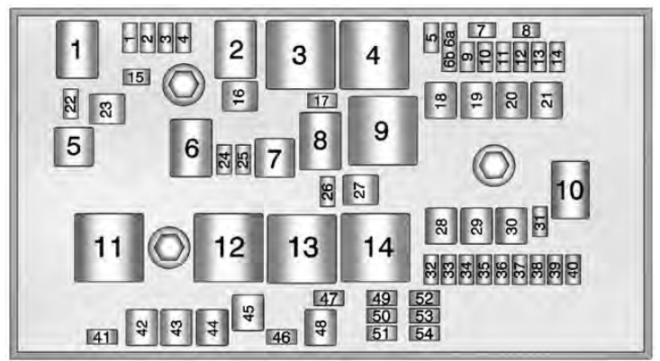
Mini Relays
Usage
3
Powertrain
4
Heated Mirrors
7
—
9
—
11
—
12
—
13
—
14
Run/Crank
Micro Relays
Circuit
1
—
2
—
6
—
8
—
10
—
Ultra Micro Relays
Circuit
5
Charge Port Door
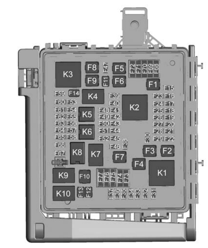
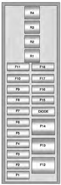
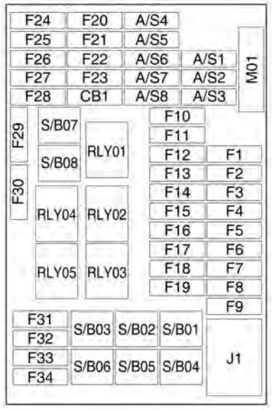
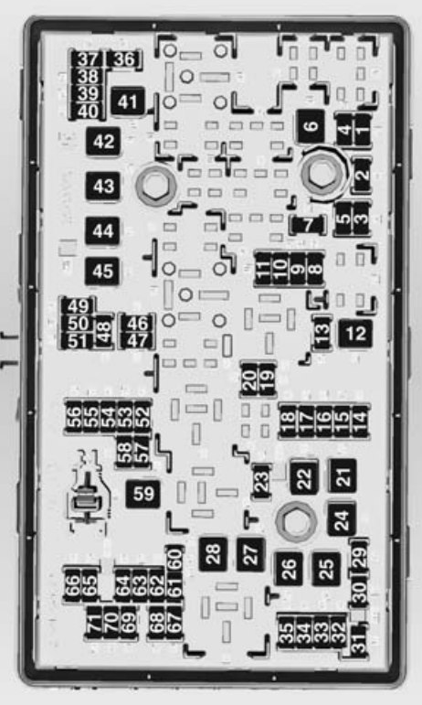
Instrument Panel Fuse box (Left Side)
The left instrument panel fuse box is on the left side end of the instrument panel.
Chevrolet Volt – fuse box – instrument panel (left side)
Fuses
Usahe
F1
Power Outlet – Top of IP Storage Bin
F2
Radio
F3
Instrument Cluster (LHD)/Hands-Free Phone (RHD)
F4
Infotainment Display
F5
Heating, Ventilation & Air Conditioning/Integrated Centre Console Switches
F6
Airbag (Sensing Diagnostic Module)
F7
Data Link Connector, Left (Primary LHD), Data Link Connector, Left (Secondary RHD)
F8
Column Lock (LHD)
F9
GSM (OnStar Data Only)
F10
Body Control Module 1/Body Control Module Electronics/Keyless Entry/Power Moding/Centre High-Mounted Stop lamp/License Plate Lamps/Left Daytime Running Lamp/Left Position Lamps/Tailgate Release Relay Control/Washer Pump Relay Control/Switch Indicator Lights
F11
Body Control Module 4/Left Headlamp
F12
Fan (RHD)
F13
—
F14
—
F15
Power Outlet (Inside Floor Console/Rear of Floor Console)
F16
—
F17
—
F18
—
Relays
Usage
R1
Retained Accessory Power Relay for Power Outlets
R2
—
R3
—
R4
Deadbolt (If Equipped LHD), Child Lockout (RHD)
Diodes
Circuit
DIODE
—
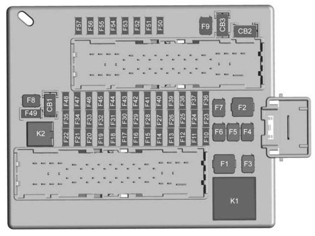
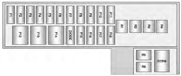
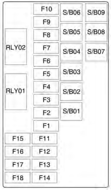
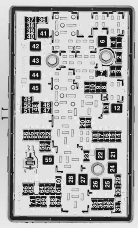
Instrument Panel Fuse box (Right Side)
The right instrument panel fuse box is on the right side end of the instrument panel.
Chevrolet Volt – fuse box – instrument panel (right side)
Fuses
Usage
F1
Steering Wheel Switch Back lighting
F2
Column Lock (RHD)
F3
Cluster (RHD)/Hands-Free Phone (LHD)
F4
Body Control Module 3/Right Headlamp
F5
Body Control Module 2/Body Control Module Electronics/Tailgate Lamp/Right Daytime Running Lamp/Shifter Lock/Switch Back lighting/Rear Fog Lamp
F6
Body Control Module 5/Retained Accessory Power Relay Control/Right Front Turn Signal Lamp/Left Rear Stop and Turn Signal Lamp/Right Position Lamps/Remote PRNDL
F7
Body Control Module 6/Map Lights/Courtesy Lights/Back-up Lamp
F8
Body Control Module 7/Left Front Turn Signal/Right Rear Stop and Turn Signal Lamp/Child Security Lock Relay Control
F9
Body Control Module 8/Locks
F10
Data Link Connector, Right (Secondary LHD), Data Link Connector, Right (Primary RHD)
F11
Intrusion and Inclination Sensor (If Equipped)
F12
Fan Motor (LHD)
F13
—
F14
—
F15
—
F16
—
F17
—
Relays
Usage
R1
—
R2
—
R3
—
R4
Deadbolt (If Equipped RHD), Child Lockout (LHD)
Diodes
Usage
DIODE
—
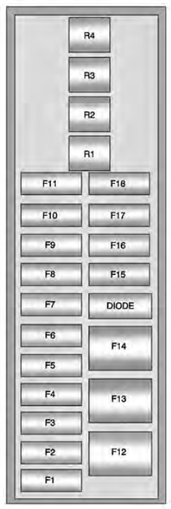
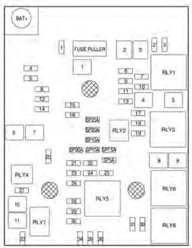
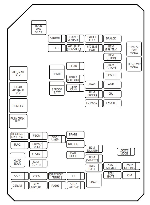
Rear compartment fuse block
The rear compartment fuse box is on the left side of the rear compartment behind a removable cover.
Chevrolet Volt – fuse box – rear compartment
Fuses
Usage
F1
—
F2
Fuel System Control Module
F3
Passive Start/Passive Entry Module
F4
Heated Seats (If Equipped)
F5
Driver Door Switches (Outside Rearview Mirror/ Charge Port Door Release/Refuel Request/Driver Window Switch)
F6
Fuel (Diurnal Valve and Evap. Leak Check Module)
F7
Accessory Power Module Cooling Fan
F8
Amplifier (If Equipped)
F9
Digital Audio Broadcast (If Equipped)
F10
Regulated Voltage Control/Ultrasonic Front and Rear Parking Assist (If Equipped)
F11
Horn
F12
Rear Power Windows
F13
Electric Parking Brake
F14
Rear Demist (Upper Grid)
F15
—
F16
Tailgate Release
F17
—
F18
—
Relays
Usage
R1
Rear Demist (Upper Grid)
R2
Tailgate Release
R3
—
R4
—
R5
—
R6
—
R7
Horn
R8
Horn
Diodes
Usage
DIODE
—
WARNING: Terminal and harness assignments for individual connectors will vary depending on vehicle equipment level, model, and market.