Chevrolet Cruze Hatchback (2013) – fuse box diagram
Year of production: 2013
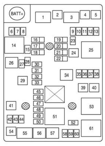
Engine compartment
The fuse box is in the front left of the engine compartment.
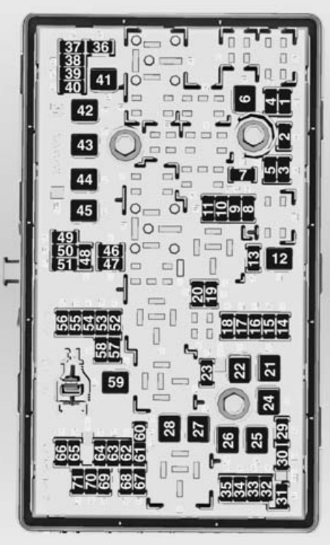
fuse box – engine compartment
| Number | Circuit |
| 1 | Transmission control module |
| 2 | Engine control module |
| 3 | — |
| 4 | Canister vent solenoid |
| 5 | Ignition |
| 6 | Front wipers |
| 7 | — |
| 8 | Fuel injection |
| 9 | Fuel injection, ignition system |
| 10 | Engine control module |
| 11 | Lambda sensor |
| 12 | Starter solenoid |
| 13 | Canister vent solenoid |
| 14 | — |
| 15 | Rear wiper |
| 16 | Ignition, Air quality sensor |
| 17 | Ignition, Airbag |
| 18 | Fuel control module |
| 19 | — |
| 20 | Fuel pump |
| 21 | Rear power windows |
| 22 | — |
| 23 | — |
| 24 | Front power windows |
| 25 | Electronic vacuum pump |
| 26 | ABS |
| 27 | Electronic key system |
| 28 | Heated rear window |
| 29 | — |
| 30 | ABS |
| 31 | Body control module |
| 32 | Body control module |
| 33 | Front seat heating |
| 34 | Sunroof |
| 35 | Infotainment system, Amplifier |
| 36 | — |
| 37 | High beam, right side |
| 38 | High beam, left side |
| 39 | — |
| 40 | — |
| 41 | — |
| 42 | Cooling fan |
| 43 | — |
| 44 | — |
| 45 | Cooling fan |
| 46 | Cooling fan |
| 47 | Lambda sensor |
| 48 | Fog lights |
| 49 | — |
| 50 | — |
| 51 | Horn |
| 52 | Instrument panel |
| 53 | Electrochromatic mirror |
| 54 | Light switch, Light control |
| 55 | Mirror folding |
| 56 | Windscreen washer |
| 57 | Steering column lock |
| 58 | — |
| 59 | Diesel fuel heating |
| 60 | Mirror heating |
| 61 | Mirror heating |
| 62 | Air condition |
| 63 | Rear window sensor |
| 64 | Air quality sensor |
| 65 | Rear fog lamp |
| 66 | Rear washer |
| 67 | Fuel system control module |
| 68 | — |
| 69 | Battery voltage sensor |
| 70 | Rain sensor |
| 71 | — |
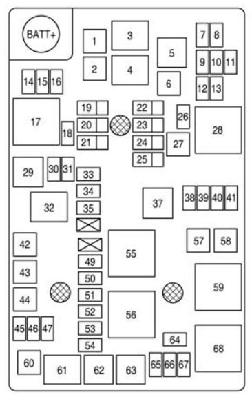
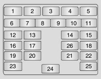
Instrument panel fuse box
The fuse box is behind the storage compartment in the instrument panel.
| Number | Circuit |
| 1 | Infotainment system, handsfree phone |
| 2 | DC/DC converter |
| 3 | Body control unit |
| 4 | Infotainment system |
| 5 | Info display, parking assist, power sounder |
| 6 | Cigarette lighter |
| 7 | Power outlet |
| 8 | Body control module |
| 9 | Body control module |
| 10 | Body control module |
| 11 | Interior fan |
| 12 | — |
| 13 | Heated seats |
| 14 | Diagnostic connector |
| 15 | Airbag |
| 16 | Central locking system, tailgate |
| 17 | Air conditioning system |
| 18 | Trailer |
| 19 | Shift lever |
| 20 | Shift lever, battery sensor |
| 21 | Instrument |
| 22 | Ignition, electronic key system |
| 23 | Body control module |
| 24 | Body control module |
| 25 | Steering column lock |
| 26 | Rear power outlet |
WARNING: Terminal and harness assignments for individual connectors will vary depending on vehicle equipment level, model, and market.