Ford Explorer XLT 4.0L 2wd (1998) – fuse box diagram
Year of production: 1998
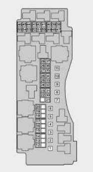
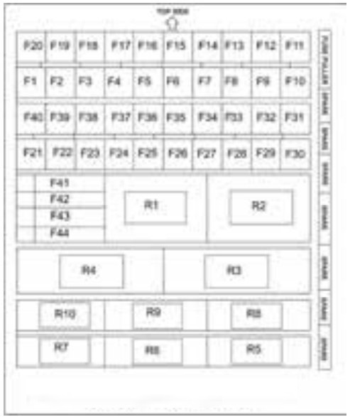
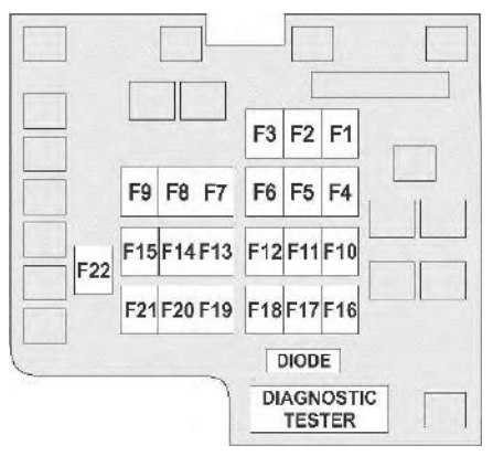
Fuse box (located under the left hand side of the instrument panel)
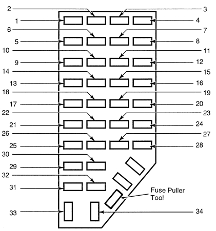
| Fuse/CB/relay | Ampere rating [A] | Description |
| 1 | 7,5 | Power mirror, power antenna |
| 2 | 7,5 | High-mount stoplamp |
| 3 | 15 | Parking lamps |
| 4 | 10 | Left headlamp |
| 5 | 10 | OBD system |
| 6 | — | Not used |
| 7 | 7,5 | Illum. switches |
| 8 | 10 | Right headlamp, fog lamp system |
| 9 | 10 | EATC memory, seat memory, message center, celluar phone |
| 10 | 7,5 | EATC system, rear blower, speed control, GEM system, brake interlock, overhead console, automatic ride control |
| 11 | 7,5 | Warning lamps |
| 12 | 10 | Front/rear wash |
| 13 | 15 | PCM system, stoplamps, 4 wheel drive, anti-lock brake, speed control, trailer tow |
| 14 | 10 | Anti-lock system |
| 15 | 7,5 | Air bag system, alternator |
| 16 | 30 | Front wiper |
| 17 | 15 | Cigar lighter |
| 18 | 15 | A/C system |
| 19 | 25 | Ignition coil, PCM system |
| 20 | 7,5 | Radio, power antenna, GEM system, anti-thef, celluar phone |
| 21 | 15 | Hazard lamps |
| 22 | 10 | Turn signals |
| 23 | — | Not used |
| 24 | 10 | Starter relay |
| 25 | 7,5 | Speedometer, GEM system |
| 26 | 10 | 4R44E/4R55E overdrive, DRL system, backup lamps, 4 wheel drive, rear defroster |
| 27 | 15 | Under hood lamp, map lights, glove box lamp, dome lamo, visior lamps, accessory delay, dimmer switch illum., 4×4 system |
| 28 | 7,5 | Memory seat, GEM system |
| 29 | 10 | Audio system |
| 30 | — | Not used |
| 31 | — | Not used |
| 32 | 7,5 | Heated mirror, heated backlite |
| 33 | 15 | High beam lamps |
| 34 | — | — |
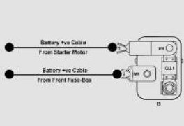
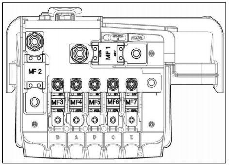
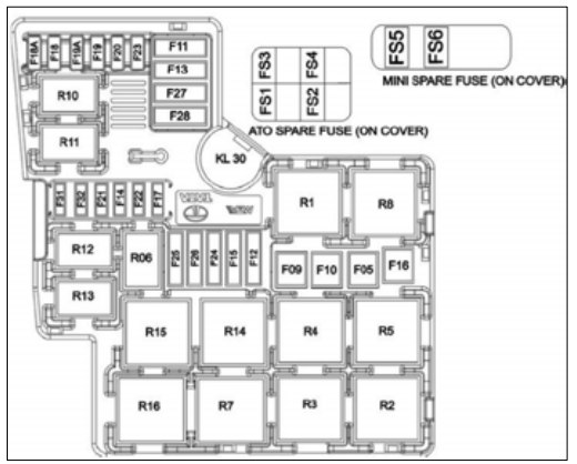
Power distribution box
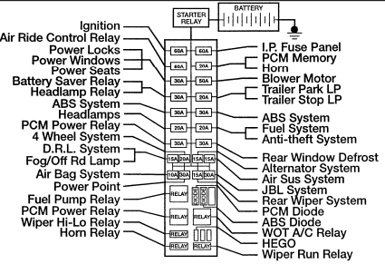
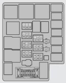
Relays
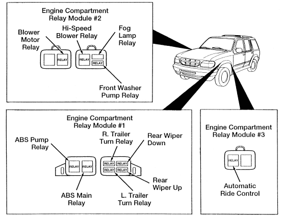
| Relays location | Relay |
| Engine compartment relay module #1 | ABS pump |
| R. trailer turn | |
| Rear wiper down | |
| Rear wiper up | |
| L. trailer turn | |
| ABS main | |
| Engine compartment relay module #2 | Blower motor |
| Hi-speed blower | |
| Fog lamp | |
| Front washer pump | |
| Engine compartment relay module #3 | Automatic ride control |
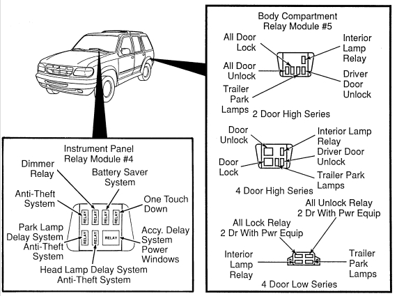
| Instrument panel relay module #4 | Dimmer |
| Battery saver system | |
| One touch down | |
| Accy. delay system power windows | |
| Head lamp delay system anti-theft system | |
| Park lamp delay system anti-theft system | |
| Anti-theft system | |
| Body compartment relay module #5 (2 door high series) | All door lock |
| All door unlock | |
| Trailer park lamps | |
| Interior lamp | |
| Driver door unlock | |
| Body compartment relay module #5 (4 door high series) | Door unlock |
| Door lock | |
| Interior lamp | |
| Driver door unlock | |
| Trailer park lamps | |
| Body compartment relay module #5 (4 door low series) | All lock relay 2 dr with pwr equip |
| All unlock 2 dr with pwr equip | |
| Trailer park lamps | |
| Interior lamp |
WARNING: Terminal and harness assignments for individual connectors will vary depending on vehicle equipment level, model, and market.