Dodge Viper (2008 – 2010) – fuse box diagram
Year of production: 2008, 2009, 2010
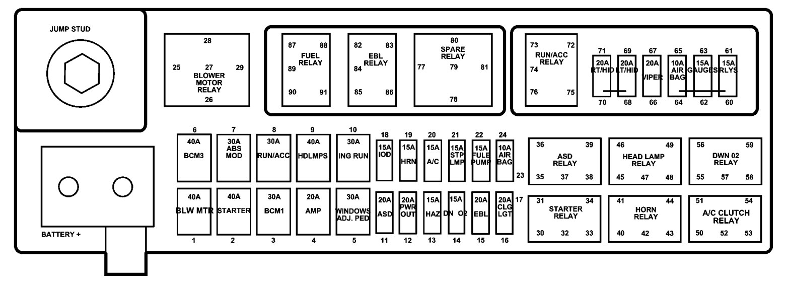
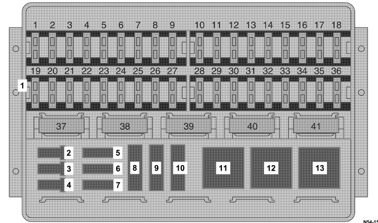
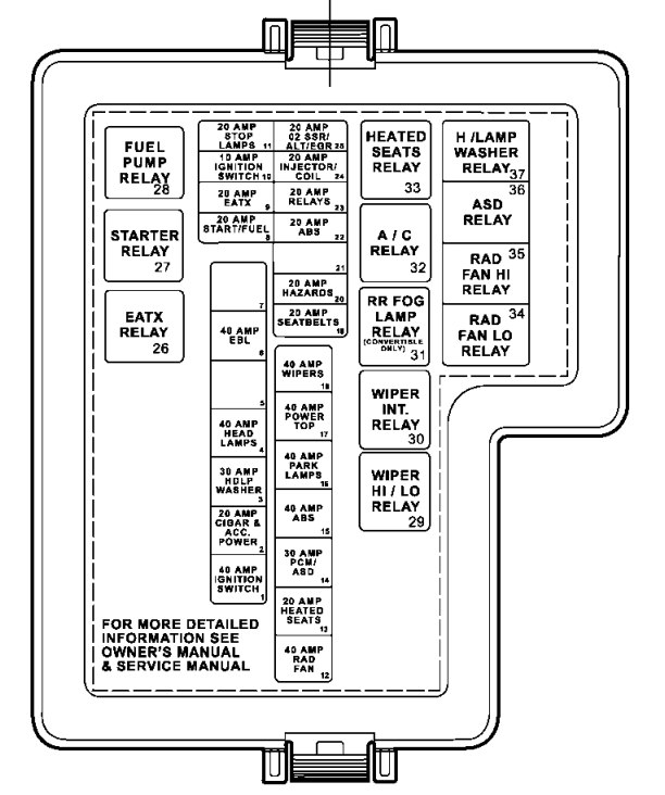
Power Distribution Center
A power distribution center is located in the engine compartment on the driver’s side of the vehicle.
| Cavity | Cartridge fuse | Mini fuse | Circuits |
| 1 | 40 | — | Blower Motor |
| 2 | 40 | — | Anti-Lock Brakes (ABS) Pump Feed/Starter |
| 3 | 30 | — | Body Control Module (BCM) – Battery Feed |
| 4 | 20 | — | Amplifier |
| 5 | 30 | — | Ignition Switch Run/Accessory Feed – Windows/Adjustable Pedals |
| 6 | 40 | — | Body Control Module (BCM) – Battery Feed |
| 7 | 30 | — | Anti-Lock Brakes (ABS) Module |
| 8 | 30 | — | Ignition Switch Run/Accessory Feed |
| 9 | 40 | — | Headlights |
| 10 | 30 | — | Ignition Switch Run Feed |
| 11 | — | 20 | Auto Shutdown Relay (ASD) |
| 12 | — | 20 | Cigar Lighter |
| 13 | — | 15 | Hazard Flasher |
| 14 | — | 20 | Auto Shutdown Relay (ASD) |
| 15 | — | 20 | Rear Window Defogger (EBL) |
| 16 | — | 20 | Selectable Power Outlet |
| 17 | |||
| 18 | — | 15 | Ignition Off Draw (IOD) |
| 19 | — | 15 | Horn |
| 20 | — | 15 | Air Conditioning (A/C) Clutch Relay |
| 21 | — | 15 | Stop Light Switch |
| 22 | — | 25 | Fuel Pump/Powertrain Control Module (PCM) |
| 23 | — | 10 | Airbag |
| 24 | |||
| 60 | — | 15 | Ignition Run/Start Relay Feed |
| 61 | |||
| 61 | — | 15 | Gauges |
| 63 | |||
| 64 | — | 10 | Airbag |
| 65 | |||
| 66 | — | 20 | Wiper Switch |
| 67 | |||
| 68 | — | 20 | Left HID Headlight |
| 69 | |||
| 70 | — | 20 | Right HID Headlight |
| 71 |
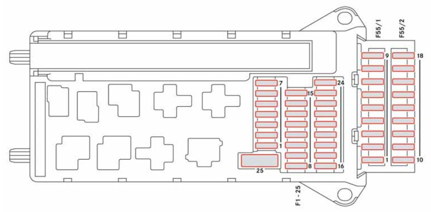
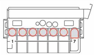
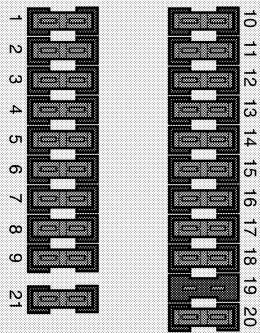
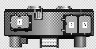
Fuses (Mini-Power Distribution Center)
A mini-power distribution center is located in the engine compartment on the passenger’s side of the vehicle.
WARNING: Terminal and harness assignments for individual connectors will vary depending on vehicle equipment level, model, and market.