Chrysler 300 (2018) – fuse box diagram
Year of production: 2018
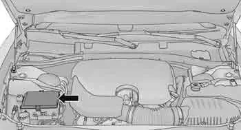
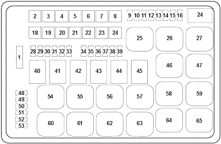
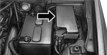
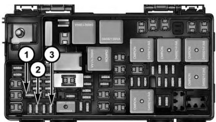
Integrated Power Module
The Integrated Power Module (IPM) is located in the engine compartment
| Cavity | Cartridge fuse | Mini fuse | Circuits |
| 1 | — | — | Fuse – Spare |
| 2 | 40 | — | Radiator Fan #1 – (Non 6.2L Supercharged) |
| 3 | 50 | — | Electric Power Steering #1 – If Equipped / Radiator Fan (6.2L Supercharged) – If Equipped |
| 4 | 30 | — | Starter |
| 5 | 40 | — | Anti Lock Brake |
| 6 | 30 | — | Anti Lock Brake |
| 7 | 20 | — | Police Ignition Run / ACC #1 |
| 8 | 50 | — | Radiator Fan (6.2L Supercharged) /Police Ignition Run / ACC # 2 |
| 20 | — | ||
| 9 | — | 20 | All-Wheel Drive Module – If Equipped |
| 10 | — | 10 | Intrusion MOD (300) – If Equipped /Under Hood Lamp – Police |
| 11 | — | 20 | Horns |
| 12 | — | 10 | Air Conditioning Clutch |
| 13 | — | — | Fuse – Spare |
| 14 | — | — | Fuse – Spare |
| 15 | — | 20 | Left HID – If Equipped |
| 16 | — | 20 | Right HID – If Equipped |
| 18 | 50 | — | Radiator Fan – (Non 6.2L Supercharged) |
| 19 | 50 | — | Electric Power Steering #2 – If Equipped |
| 20 | 30 | — | Wiper Motor |
| 21 | 30 | — | Headlamp Washers – If Equipped Police Bat Feed #2 |
| 22 | 40 | — | Engine Cooling Pump (6.2L Supercharged) / Police Bat Feed # 3 |
| 20 – Police | — | ||
| 23 | 20 | — | Police Bat Feed # 1 |
| 24 | 20 | — | Radiator Fan (6.2L Supercharged) / Police Ignition Run/ACC Feed # 3 |
| 28 | — | — | Fuse – Spare |
| 29 | — | 15 | Transmission Control Module (Challenger/Charger Police) / Electronic Shift Module (Challenger) |
| 30 | — | — | Fuse – Spare |
| 31 | — | 25 | Engine Module |
| 32 | — | — | Fuse – Spare |
| 33 | — | — | Fuse – Spare |
| 34 | — | 25 | Powertrain #1 |
| 35 | — | 20 | Powertrain #2 |
| 36 | — | 10 | Anti-Lock Brake Module |
| 37 | — | 10 | Engine Controller / Rad Fan Relays (Charger/300) / Electric Power Steering Module (Charger/300) / 5-Speed TCM |
| 38 | — | 10 | Airbag Module |
| 39 | — | 10 | EPS (Challenger) / EHPS (Police) / AC Clutch Relay / Vacuum Pump Relay / Rad Fan Relays (Challenger) |
| 48 | — | 10 | AWD Module/Front Axle Disconnect – If Equipped |
| 49 | — | — | Fuse – Spare |
| 50 | — | — | Fuse – Spare |
| 51 | — | 20 | Vacuum Pump |
| 52 | — | 5 | Adaptive Cruise – If Equipped |
| 53 | — | — | Fuse – Spare |
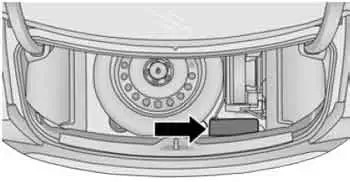
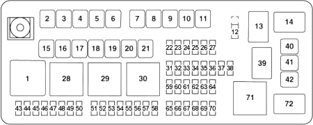
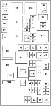
Rear Power Distribution Center
There is also a power distribution center located in the trunk under the spare tire access panel. This center contains fuses and relays.
| Cavity | Cartridge fuse | Mini fuse | Circuits |
| 2 | 60 | — | Front PDC Feed #1 |
| 3 | — | — | Fuse – Spare |
| 4 | 60 | — | Front PDC Feed #2 |
| 5 | 30 | — | Sunroof / Dome Lamp – Police |
| 6 | 40 | — | Exterior Lighting #1 |
| 7 | 40 | — | Exterior Lighting #2 |
| 8 | 30 | — | Interior Lighting |
| 9 | 30 | — | Power Locks |
| 10 | 30 | — | Driver Door Control Module |
| 11 | 30 | — | Passenger Door Control Module |
| 12 | — | 20 | Dual USB Center Console Rear/Cigar Lighter IP – If Equipped |
| 15 | 40 | — | HVAC Blower |
| 16 | 20 | — | Left Spot Lamp – Police |
| 17 | 20 | — | Right Spot Lamp – Police |
| 18 | 30 | — | Mod Network Interface – Police |
| 19 | — | — | Fuse — Spare |
| 20 | — | — | Fuse — Spare |
| 21 | 30 | — | Fuel Pump (Non 6.2L SRT Demon) |
| 22 | — | 5 | Cyber Gateway Mod |
| 23 | — | 10 | Fuel Door/Diagnostic Port |
| 24 | — | 10 | Integrated Center Stack |
| 25 | — | 10 | Tire Pressure Monitor |
| 26 | — | 15 | Cygnus Transmission Module (Charger/300) / Electronic Shift Module (Charger/300) |
| 27 | — | 25 | Amplifier – If Equipped |
| 31 | — | 25 | Power Seats – If Equipped |
| 32 | — | 15 | HVAC Module/Cluster |
| 33 | — | 15 | Ignition Switch/RF Hub Module/Steering Column Lock (300) – If Equipped |
| 34 | — | 10 | Steering Column Module/Clock (300) |
| 35 | — | 10 | Battery Sensor |
| 36 | — | 15 | Electronic Exhaust Valve – If Equipped |
| 37 | — | 20 | Radio |
| 37 | — | 20 | Power Outlet Inside Arm Rest/Console Media Hub |
| 40 | 30 | — | Fuel Pump (6.2L SRT Demon – If Equipped) |
| 41 | 30 | — | Fuel Pump (6.2L SRT Demon – If Equipped) |
| 42 | 30 | — | Rear Defrost |
| 43 | — | 20 | Comfort Seat And Steering Wheel Module (Heated Steering Wheel/RR Heated Seats) |
| 44 | — | 10 | Park Assist / Blind Spot /Rear View Camera |
| 45 | — | 15 | Cluster / Rearview Mirror / Compass (Charger/300) / Humidity Sensor / Forward Facing Camera (Lane Departure) / Cyber Gateway |
| 46 | — | — | Fuse — Spare |
| 47 | — | 10 | Adaptive Front Lighting / Day Time Running Lamps – If Equipped |
| 48 | — | 20 | Active Suspension – (6.4L / 6.2L) |
| 49 | — | — | Fuse — Spare |
| 50 | — | — | Fuse — Spare |
| 51 | — | 20 | Front Heated / Vented Seats – If Equipped |
| 52 | — | 10 | Heated Cupholders/Rear Heated Seat Switches – If Equipped |
| 53 | — | 10 | HVAC Module/In Vehicle Temperature Sensor |
| 54 | — | — | Fuse – Spare |
| 55 | — | — | Fuse — Spare |
| 56 | — | — | Fuse — Spare |
| 57 | — | — | Fuse — Spare |
| 58 | — | 10 | Airbag Module |
| 59 | — | 20 | Adjustable Pedals – Police |
| 60 | — | — | Fuse – Spare |
| 61 | — | — | Fuse – Spare |
| 62 | — | — | Fuse — Spare |
| 63 | — | — | Fuse — Spare |
| 64 | — | 25 | Rear Windows (Charger/300) |
| 65 | — | 10 | Airbag Module |
| 66 | — | — | Fuse — Spare |
| 67 | — | 10 | Rain and Light Sensor / Sunroof / Inside RR View Mirror / Police Run Acc Relay |
| 68 | — | 10 | Dual USB Power Outlet – R/A Sense (Charger/300) Rear Sunshade (Charger/ 300) RR USB Timer |
| 69 | — | — | Fuse — Spare |
| 70 | — | — | Fuse — Spare |
WARNING: Terminal and harness assignments for individual connectors will vary depending on vehicle equipment level, model, and market.