Chrysler Sebring Sedan (2010) – fuse box diagram
Year of production: 2010
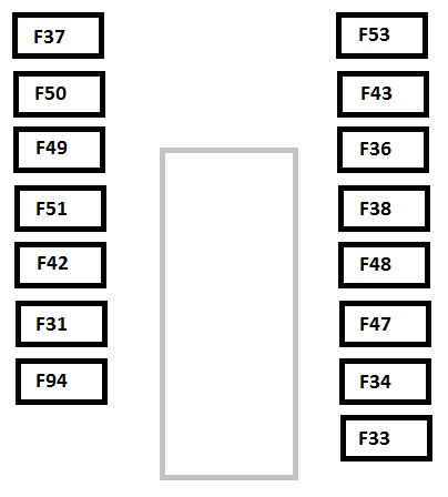
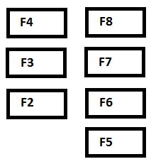
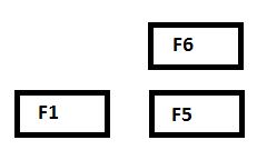
Totally integrated power (TIPM)
Totally Integrated Power Module (TIPM) is located in the engine compartment near the air cleaner assembly.
| Cavity | Cartridge fuse | Mini fuse | Description |
| 1 | 40 | — | Power Top Module (If Equipped) |
| 2 | — | 20 | AWD Module |
| 3 | — | 10 | Battery Feed — Center High Mounted Stop Light (CHMSL)/Brake Switch |
| 4 | — | 10 | Battery Feed — Ignition Switch |
| 5 | — | 20 | Trailer Tow — If Equipped |
| 6 | — | 10 | Ignition Off Draw (IOD) — Power Mirror Switch/Climate Controls |
| 7 | — | 30 | Ignition Off Draw (IOD) Sense 1 |
| 8 | — | 30 | Ignition Off Draw (IOD) Sense 2 |
| 9 | 40 | — | Battery Feed — Power Seats – if equipped/PZEV Air Pump – if equipped |
| 10 | — | 20 | Battery Feed — Cabin Compartment Node (CCN) |
| 11 | — | 15 | Selectable Power Outlet |
| 12 | — | 20 | — |
| 13 | — | 20 | — |
| 14 | — | 10 | Ignition Off Draw (IOD) — Cabin Compartment Node (CCN)/ Interior Lighting |
| 15 | 40 | — | Battery Feed — Radiator Fan Relay |
| 16 | — | 15 | IGN Run/ACC — Cigar Lighter/PWR Sunroof Mod |
| 17 | — | 10 | Ignition Off Draw (IOD) — Wireless Control Module (WCM)/Clock/Steering Control Module (SCM) |
| 18 | 40 | — | Battery Feed — Auto Shutdown (ASD) Relay |
| 19 | — | 20 | Ignition Off Draw (IOD) — Power Amp Feed 2 – if equipped |
| 20 | — | 15 | Ignition Off Draw (IOD) — Radio |
| 21 | — | 10 | — |
| 22 | — | 10 | Ignition Run — Climate Controls/Hot Cupholder – if equipped |
| 23 | — | 15 | Auto Shutdown (ASD) Relay Feed 3 |
| 24 | — | 25 | Battery Feed — PWR Sunroof Feed |
| 25 | — | 10 | Ignition Run — Heated Mirrors – If Equipped |
| 26 | — | 15 | Auto Shutdown (ASD) Relay Feed 2 |
| 27 | — | 10 | Ignition Run — Occupant Classification Module (OCM)/Occupant Restraint Controller (ORC) |
| 28 | — | 10 | Ignition Run — Occupant Classification Module (OCM)/Occupant Restraint Controller (ORC) |
| 29 | — | — | Hot Car (No Fuse Required) |
| 30 | — | 20 | Ignition Run — Heated Seats – If Equipped |
| 31 | — | 10 | — |
| 32 | 30 | — | Auto Shutdown (ASD) Relay Feed 1 |
| 33 | — | 10 | Battery Feed — Switch Bank/Diagnostic Link Connector/ Powertrain Control Module (PCM) |
| 34 | 30 | — | Battery Feed — Anti-Lock Brakes (ABS) Module – if equipped/ Electronic Stability Program (ESP) Module – If Equipped |
| 35 | 40 | — | Battery Feed — Anti-Lock Brakes (ABS) Module – If Equipped/Electronic Stability Program (ESP) Module – If Equipped |
| 36 | 30 | — | Battery Feed — Passenger Door Module (PDM)/Driver Door Module (DDM) |
| 37 | — | 15 | Power Top Module (If Equipped) |
WARNING: Terminal and harness assignments for individual connectors will vary depending on vehicle equipment level, model, and market.