Dodge Diesel (2006) – fuse box diagram

Dodge Diesel (2006) – fuse box diagram

Year of  production: 2006

Integrated power module

Cavity Cartridge fuse Mini Fuse Description
1 20 Power Outlet Console
2 20 CCN Door Locks/BTSI
3 20 Spare
4 20 Spare
5 20 Power Sunroof
6 10 OCM/VIST Fan/Wastegate
7 15 Reverse Lockout Solenoid Battery (SRT-10 Only)
8 10 Heated Mirrors
9 30 Off Road Module Power
10 5 Trx-Off Rd Pkg Sen (Gas Engine Only)
11 20 IOD-CNN/Radio/Under Hood Lamp/WCM/SDARS/HFM
12 30 Electric Brake
13 25 Power-Battery RWAL/ABS Module Feed
14 15 Park Lamps Left
15 20 Trailer Park Lamps
16 15 Park Lamps Right
17 15 Spare
18 40 ABS Pump
19 30 Trailer Tow
20 10 ORC2
21 10 ORC Preset Carrier
22 2 IGN Switch Feed
23 10 ECM/WCM/HVC
24 20 Subwoofer Amplifier (SRT-10 Only)
25 10 Power Mirror
26 20 Brake Switch/ CHMSL/Stop Lamp
27 40 Power Seats
28 10 Power Run/Start-NCC/WCM/ABS/RWAL
29 10 Switches/EC Mirror/Smart Bar
30 15 Spare
31 10 PCM/Transfer Case Brake
32 10 HVAC/Ajustable Pedals/Heated Seats Switch LED/Exhaust Brake
33 10 Power-IGN Run Misc
34 10 Spare
35 15 CNN Illumination
36 25 Audio_Amplifier
37 15 Spare
38 20 Power Outlet IP
39 10 Sunroof/Seatbelt Tensioner
40 20 Cigar Lighter
41 25 Spare
42 30 Diesel PCM (Diesel Only)

WARNING: Terminal and harness assignments for individual connectors will vary depending on vehicle equipment level, model, and market.

Dodge Dart (2015 – 2016) – fuse box diagram

Dodge Dart (2015 – 2016) – fuse box diagram

Year of  production: 2015, 2016

Interior Fuses

Cavity Cartridge fuse Mini Fuse Description
F1 20 Front Heated Seats – If Equipped
F2 20 Rear Heated Seats, Heated Steering Wheel – If Equipped
F3 10 Park Assist Module, Rear Camera, Left and Right Blind Spot Sensor, Compass – If Equipped
F4 15 Instrument Cluster
F5 10 HVAC, Humidity Sensor, In-Car Temperature Sensor, Inside Mirror Assembly
F18 15 Radio
F20 10 Steering Column Control Module, Switch Bank
F21 10 Diagnostic Port
F22 10 Universal Garage Door Opener, EOM
F23 20 Sunroof
F24 5 Run/Accessory Relay
F25 5 Transmission Control Module #4
F26 5 Stop Lamp Switch
F27 10 Pneumatic Lumbar Support


Underhood Fuses

The Power Distribution Center is located on the right side of the engine compartment, behind the battery.

Cavity Cartridge fuse Mini Fuse Description
F01 70 Body Control Module #1
F02 60 Body Control Module #2
F03 30 Output For Starter Relay #1
F04 40 ESC Pump Motor
F05 40 Transmission Control Module #1
F06 30 Body Control Module #3
F07 40 EBL RLY Coil, Blower Motor RLY Coil
F09 5 Radiator Fan
F10 10 ORC
F11 20 Run/Start, Engine Control Module
F14 15 Transmission Control Module #2
F15 15 Transmission Control Module #3
F16 15 Engine Control Module, Ignition Coils
F17 15 Brake System Module
F18 20 Engine Control Module
F19 10 A/C Compressor Clutch
F20 30 Rear Defroster (EBL)
F21 20 Fuel Pump
F22 10 Occupant Restraint Controller
F23 25 Brake System Module
F24 20 Engine Control Module, Fuel Injectors
F30 20 Power Outlet (Console)
F81 60 Interior PDC Battery Feed, Power Seats
F82 30 Amplifier
F83 40 HVAC Blower Motor
F84 20 Cigar Lighter
F85 10 Sunroof, LRSM, Power Outlet (Console), UCI/AUX Port, Cigar Lighter
F86 20
F87 10 Wastegate, Purge Solenoid, OBD Vent Valve, Oxygen Sensor Heaters
F88 10 Heated Outside Mirrors


Body Control Module (BCM) Fuses

Cavity Cartridge fuse Mini Fuse Description
F12 Spare
F13 15 Left Headlamp
F31 Spare
F32 10 Interior Lighting/Decklid/Liftgate Release
F33 25 Window Motor – Driver
F34 25 Window Motor – Passenger
F36 15 Intrusion Module
F37 10 Instrument Panel Cluster
F38 20 Door Locks
F42 Spare
F43 20 Windshield Washer Pump
F47 5 Transmission Control Module (Tcm)
F48 20 Spare
F49 7,5 Stop Lamp Switch
F50 7,5 Pneumatic Lumbar Support
F51 7,5 Cd/Hands-Free Module – Bluetooth/Radio Display
F53 7,5 Driver Window Switch/Power Mirrors
F89 5 Trunk Lamp
F90 7,5 Front Fog Lamps – Right
F91 7,5 Front Fog Lamps – Left
F92 7,5 High Beams (Shutters)
F93 15 Right Headlamp

WARNING: Terminal and harness assignments for individual connectors will vary depending on vehicle equipment level, model, and market.

Dodge Dart (2014) – fuse box diagram

Dodge Dart (2014) – fuse box diagram

Year of  production: 2014

Interior Fuses

Cavity Cartridge fuse Mini Fuse Description
F1 20 Front Heated Seats – If Equipped
F2 20 Rear Heated Seats, Heated Steering Wheel – If Equipped
F3 10 Park Assist Module, Rear Camera, Left and Right Blind Spot Sensor, Compass – If Equipped
F4 15 Instrument Cluster
F5 10 HVAC, Humidity Sensor, In-Car Temperature Sensor, Inside Mirror Assembly
F18 15 Radio
F19 10 Fuel Door
F20 10 Steering Column Control Module, Switch Bank
F21 10 Diagnostic Port
F22 10 Universal Garage Door Opener, EOM
F23 20 Sunroof
F24 5 Run/Accessory Relay
F25 5 Transmission Control Module #4
F26 5 Stop Lamp Switch
F27 10 Pneumatic Lumbar Support


Underhood Fuses

The Power Distribution Center is located on the right side of the engine compartment, behind the battery.

Cavity Cartridge fuse Mini Fuse Description
F01 70 Body Control Module #1
F02 60 Body Control Module #2
F03 30 Output For Starter Relay #1
F04 40 ESC Pump Motor
F05 40 Transmission Control Module #1
F06 30 Body Control Module #3
F07 40 EBL RLY Coil, Blower Motor RLY Coil
F09 5 Radiator Fan
F10 10 ORC
F11 20 Run/Start, Engine Control Module
F14 15 Transmission Control Module #2
F15 15 Transmission Control Module #3
F16 15 Engine Control Module, Ignition Coils
F17 15 Brake System Module
F18 20 Engine Control Module
F19 10 A/C Compressor Clutch
F20 30 Rear Defroster (EBL)
F21 20 Fuel Pump
F22 10 Occupant Restraint Controller
F23 25 Brake System Module
F24 20 Engine Control Module, Fuel Injectors
F30 20 Power Outlet (Console)
F81 60 Interior PDC Battery Feed, Power Seats
F82 30 Amplifier
F83 40 HVAC Blower Motor
F84 20 Cigar Lighter
F85 10 Sunroof, LRSM, Power Outlet (Console), UCI/AUX Port, Cigar Lighter
F86 20
F87 10 Wastegate, Purge Solenoid, OBD Vent Valve, Oxygen Sensor Heaters
F88 10 Heated Outside Mirrors


Body Control Module (BCM) Fuses

Cavity Cartridge fuse Mini Fuse Description
F12 Spare
F13 15 Left Headlamp
F31 Spare
F32 10 Interior Lighting/Decklid/Liftgate Release
F33 25 Window Motor – Driver
F34 25 Window Motor – Passenger
F36 15 Intrusion Module
F37 10 Instrument Panel Cluster
F38 20 Door Locks
F42 Spare
F43 20 Windshield Washer Pump
F47 5 Transmission Control Module (Tcm)
F48 20 Spare
F49 7,5 Stop Lamp Switch
F50 7,5 Pneumatic Lumbar Support
F51 7,5 Cd/Hands-Free Module – Bluetooth/Radio Display
F53 7,5 Driver Window Switch/Power Mirrors
F89 5 Trunk Lamp
F90 7,5 Front Fog Lamps – Right
F91 7,5 Front Fog Lamps – Left
F92 7,5 High Beams (Shutters)
F93 15 Right Headlamp

WARNING: Terminal and harness assignments for individual connectors will vary depending on vehicle equipment level, model, and market.

Dodge Dart (2013) – fuse box diagram

Dodge Dart (2013) – fuse box diagram

Year of  production: 2013

Interior Fuses

Cavity Cartridge fuse Mini Fuse Description
F1 20 Front Heated Seats
F2 20 Rear Heated Seats, Heated Steering Wheel
F3 10 PAM, Rear Camera, LBSS, RBSS, Compass
F4 15 IPC
F5 10 HVAC, Humidity Sensor, In-Car Temperature Sensor, Inside Mirror Assembly
F18 15 Radio
F19 10 Fuel Door
F20 10 SCCM, SAS, Switch Bank
F21 10 Diagnostic Port
F22 10 UGDO, EOM
F23 20 Sunroof
F24 5 Direct Battery For Underhood PDC (RLY Coils)
F25 5 DDCT Feed #4
F26 5 Stop Lamp Switch
F27 10 Pneumatic Lumbar Support (Solenoid), Pneumatic Lumbar Support (Pump Motor)


Integrated Power Module

Cavity Cartridge fuse Mini Fuse Description
F01 70 Direct Battery Feed #1 To BCM
F02 60 Direct Battery Feed #2 To BCM
F03 30 Output For Starter Relay #1
F04 40 ESP Pump Motor
F05 40 DDCT Feed #1 (SDU)
F06 30 Direct Battery Feed #3 To BCM
F07 40 EBL RLY Coil, Blower Motor RLY Coil
F09 5 Radiator Fan Enable RLY, Radiator Fan Enable RLY Coil
F10 10 ORC
F11 20 ECM, EPS, Backup Lamp Switch
F14 15 DDCT Feed #2
F15 15 DDCT Feed #3
F16 15 Ignition Coils, Coil Capacitor
F17 15 ESC, Brake Pedal Switch, OCM
F18 20 ECM
F19 10 A/C Compressor Clutch
F20 30 EBL
F21 20 Fuel Pump
F22 10 ORC
F23 25 ESC
F24 20 ECM, Fuel Injectors, Active Grill Shutter (AGS)
F30 20 Power Outlet (Console)
F81 60 Interior PDC Battery Feed, Power Seats
F82 30 Amplifier
F83 40 HVAC Blower Motor
F84 20 Cigar Lighter
F85 10 Sunroof, LRSM, Power Outlet (Console), UCI/AUX Port, Cigar Lighter
F86 20
F87 10 Wastegate, Purge Solenoid, OBD Vent Valve, Oxygen Sensor Heaters
F88 10 Heated Outside Mirrors

WARNING: Terminal and harness assignments for individual connectors will vary depending on vehicle equipment level, model, and market.

Dodge Dakota (2011) – fuse box diagram

Dodge Dakota (2011) – fuse box diagram

Year of  production: 2011

Power Distribution center

Cavity Cartridge fuse Mini Fuse Description
1 Spare
2 Spare
3 30 Electric Brake
4 50 Power Seat
5 Spare
6 20 Ignition Off Draw (IOD) Cabin Compartment Node (CCN), Radio
7 10 Powertrain Control Module (PCM)/Fuel/RAD/AC Coils
8 10 Cabin Compartment Node (CCN)/Mirror/4×4
9 Spare
10 2 Low Current Ignition Switch
11 10 AC Clutch
12 15 Trailer Tow Lt Stop/Turn
13 15 Trailer Tow Rt Stop/Turn
14 20 Ignition Off Draw (IOD) #2
15 25 Trans/Powertrain Control Module (PCM)
16 20 Horn
17 20 Antilock Brakes Feed (Valves)
18 20 Fuel Pump
19 15 Rear Center Brake Lamp
20 20 Instrument Cluster/Door Locks/Brake Transmission Shift Interlock
21 25 Audio Amp
22 20 Power Outlet (Switchable)
23 20 Fog Lamps
24 20 Powertrain Control Module B+
25 15 Instrument Cluster Illumination
26  20 Ignition Run/Start Feed
27 10 Power Mirror
28 20 Power Outlet
29 20 Body Control Module 4 (Wipers)
30 Spare
31  30 Ignition Run/AC/Windows
32 30 Body Control Module 1 (Ext. Lights # 1)
33 30 Automatic Shutdown
34 30 Body Control Module 2 (Ext. Light # 2)
35 40 Climate Control System Blower Motor
36 Spare
37 Spare
38 20 Spare
39 30 Starter Solenoid
40  40 Ignition Run Feeds
41 30 Wiper Motor
42 25 Body Control Module 5 (T-Case)
43 10 Lt Park Lamps
44 10 Rt Park Lamps
45 20 Trailer Tow Park Lamps
46 10 Airbag System # 2
47 40 Spare
48 20 Sunroof/Sound Box
49 30 Trailer Tow B+
50 40 Antilock Brakes Module (Pump)
51 40 Park Lamps
52 Spare
53 40 Rear Defogger
54 Spare
55 Spare
56 10 Heated Seats
57 20 Airbag System # 2
58 20 Heated Seats
59 10 Climate Control System Module
60 10 Antilock Brakes Module
61 20 Body Control Module 3 (Reverse Lamps)

WARNING: Terminal and harness assignments for individual connectors will vary depending on vehicle equipment level, model, and market.

Dodge Dakota (2009 – 2010) – fuse box diagram

Dodge Dakota (2009 – 2010) – fuse box diagram

Year of  production: 2009, 2010

Power Distribution center

Cavity Cartridge fuse Mini Fuse Description
1 Spare
2 Spare
3 30 Electric Brake
4 50 Power Seat
5 Spare
6 20 Ignition Off Draw (IOD) Cabin Compartment Node (CCN), Radio
7 10 Powertrain Control Module (PCM)/Fuel/RAD/AC Coils
8 10 Cabin Compartment Node (CCN)/Mirror/4×4
9 Spare
10 2 Low Current Ignition Switch
11 10 AC Clutch
12 15 Trailer Tow Lt Stop/Turn
13 15 Trailer Tow Rt Stop/Turn
14 20 Ignition Off Draw (IOD) #2
15 25 Trans/Powertrain Control Module (PCM)
16 20 Horn
17 20 Antilock Brakes Feed (Valves)
18 20 Fuel Pump
19 15 Center High Mounted Stop Lamp (CHMSL)
20 20 Cabin Compartment Node (CCN) Door Locks/Brake Transmission Shift Interlock (BTSI)
21 25 Audio Amp
22 20 Power Outlet (Switchable)
23 20 Fog Lamps
24 20 Powertrain Control Module (PCM) B+
25 15 Cabin Compartment Node (CCN) Illumination
26  20 Ignition Run/Start Feed
27 10 Power Mirror
28 20 Power Outlet
29 20 Front Control Module (FCM) 4 (Wipers)
30 Spare
31  30 Ignition Accessory Feed
32 30 Front Control Module (FCM) 1 (Ext. Lights # 1)
33 30 Auto Shut Down (ASD)
34 30 Front Control Module (FCM) 2 (Ext. Light # 2)
35 40 HVAC Blower Motor
36 Spare
37 Spare
38 20 Spare
39 30 Starter Solenoid
40  40 Ignition Run Feeds
41 30 Wiper Motor
42 25 Front Control Module (FCM) 5 (T-Case)
43 10 Lt Park Lamps
44 10 Rt Park Lamps
45 20 Trailer Tow Park Lamps
46 10 Airbag System # 2
47 40 Spare
48 20 Sunroof/Sound Box
49 30 Trailer Tow B+
50 40 Anti-Lock Brake System (ABS) Module (Pump)
51 40 Park Lamps
52 Spare
53 40 Rear Defogger
54 Spare
55 Spare
56 10 Heated Seats
57 20 Airbag System # 2
58 20 Heated Seats
59 10 HVAC Module
60 10 ABS Module
61 20 Front Control Module (FCM) 3 (Reverse Lamps)

WARNING: Terminal and harness assignments for individual connectors will vary depending on vehicle equipment level, model, and market.

Dodge Dakota (2008) – fuse box diagram

Dodge Dakota (2008) – fuse box diagram

Year of  production: 2008
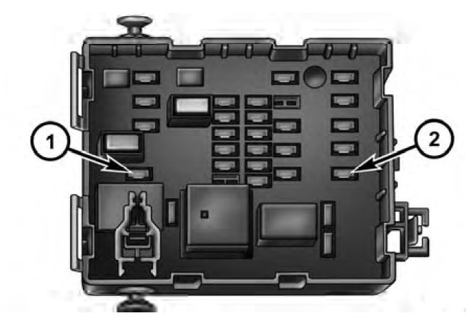
Power Distribution center

Cavity Cartridge fuse Mini Fuse Description
1 Spare
2 40 Ignition Accessory (ACC)
3 30 Electric Brake
4 50 Power Seat
5 40 Ignition Run Only
6 20 Ignition Off Draw (IOD) Cabin Compartment Node (CCN), Radio
7 10 Powertrain Control Module (PCM)/Fuel/RAD/AC Coils
8 10 Cabin Compartment Node (CCN)/Mirror/4×4
9 10 Airbag System #3
10 Spare
11 10 AC Clutch
12 15 T Tow Lt Stop/Turn
13 15 Trailer Tow Rt Stop/Turn
14 20 Ignition Off Draw (IOD) #2
15 25 Trans/Powertrain Control Module (PCM)
16 20 Horn
17 20 ABS Feed (Valves)
18 20 Fuel Pump
19 15 Center High Mounted Stop Lamp (CHMSL)
20 20 Cabin Compartment Node (CCN) Door Locks/Brake Transmission Shift Interlock (BTSI)
21 25 Audio Amp
22 20 Power Outlet (Switchable)
23 20 Fog Lamps
24 20 Powertrain Control Module (PCM) B+
25 15 Cabin Compartment Node (CCN) Illumination
26 Spare
27 10 Power Mirror
28 20 Power Outlet
29 20 Front Control Module (FCM) 4 (Wipers)
30 Spare
31 Spare
32 30 Front Control Module (FCM) 1 (Ext. Lights # 1)
33 30 Auto Shut Down (ASD)
34 30 Front Control Module (FCM) 2 (Ext. Light # 2)
35 40 HVAC Blower Motor
36 10 Ignition UNLK/RN/ST
37 10 Crank
38 20 Run/Start
39 30 Starter Solenoid
40 Spare
41 30 Wiper Motor
42 25 Front Control Module (FCM) 5 (T-Case)
43 10 Lt Park Lamps
44 10 Rt Park Lamps
45 20 Trailer Tow Park Lamps
46 10 Airbag System # 2
47 40 Ignition Run/Accessory (Acc)
48 20 Sunroof/Sound Box
49 30 Trailer Tow B+
50 40 Anti-Lock Brake System (ABS) Module (Pump)
51 40 Park Lamps
52 Spare
53 40 Rear Defogger
54 Spare
55 10 Cabin Compartment Node (CCN) Accessory (ACC) Feed
56 10 Heated Seats
57 20 Airbag System # 2
58 20 Heated Seats
59 10 HVAC Module
60 10 ABS Module
61 20 Front Control Module (FCM) 3 (Reverse Lamps)

WARNING: Terminal and harness assignments for individual connectors will vary depending on vehicle equipment level, model, and market.

Dodge Dakota (2007) – fuse box diagram

Dodge Dakota (2007) – fuse box diagram

Year of  production: 2007

Power Distribution center

Cavity Cartridge fuse Mini Fuse Description
1 Spare
2 40 Ignition Accessory (ACC)
3 30 Electric Brake
4 50 Power Seat
5 40 Ignition Run Only
6 20 Ignition Off Draw (IOD) Cabin Compartment Node (CCN), Radio
7 10 Powertrain Control Module (PCM)/Fuel/RAD/AC Coils
8 10 Cabin Compartment Node (CCN)/Mirror/4×4
9 10 Airbag System #3
10 Spare
11 10 AC Clutch
12 15 T Tow Lt Stop/Turn
13 15 Trailer Tow Rt Stop/Turn
14 20 Ignition Off Draw (IOD) #2
15 25 Trans/Powertrain Control Module (PCM)
16 20 Horn
17 20 ABS Feed (Valves)
18 20 Fuel Pump
19 15 Center High Mounted Stop Lamp (CHMSL)
20 20 Cabin Compartment Node (CCN) Door Locks/Brake Transmission Shift Interlock (BTSI)
21 25 Audio Amp
22 20 Power Outlet (Switchable)
23 20 Fog Lamps
24 20 Powertrain Control Module (PCM) B+
25 15 Cabin Compartment Node (CCN) Illumination
26 Spare
27 10 Power Mirror
28 20 Power Outlet
29 20 Front Control Module (FCM) 4 (Wipers)
30 Spare
31 Spare
32 30 Front Control Module (FCM) 1 (Ext. Lights # 1)
33 30 Auto Shut Down (ASD)
34 30 Front Control Module (FCM) 2 (Ext. Light # 2)
35 40 HVAC Blower Motor
36 10 Ignition UNLK/RN/ST
37 10 Crank
38 20 Run/Start
39 30 Starter Solenoid
40 Spare
41 30 Wiper Motor
42 25 Front Control Module (FCM) 5 (T-Case)
43 10 Lt Park Lamps
44 10 Rt Park Lamps
45 20 Trailer Tow Park Lamps
46 10 Airbag System # 2
47 40 Ignition Run/Accessory (Acc)
48 20 Sunroof/Sound Box
49 30 Trailer Tow B+
50 40 Anti-Lock Brake System (ABS) Module (Pump)
51 40 Park Lamps
52 Spare
53 40 Rear Defogger
54 Spare
55 10 Cabin Compartment Node (CCN) Accessory (ACC) Feed
56 10 Heated Seats
57 20 Airbag System # 2
58 20 Heated Seats
59 10 HVAC Module
60 10 ABS Module
61 20 Front Control Module (FCM) 3 (Reverse Lamps)

WARNING: Terminal and harness assignments for individual connectors will vary depending on vehicle equipment level, model, and market.

Dodge Dakota (2006) – fuse box diagram

Dodge Dakota (2006) – fuse box diagram

Year of  production: 2006

Power Distribution center

Cavity Cartridge fuse Mini Fuse Description
1 Spare
2 40 Ignition ACC
3 30 Elect Brake
4 50 Power Seat
6 20 Ignition Run Only
7 10 PCM/Fuel/RAD/AC Coils
8 10 CCN/Mirr/4×4
9 10 Airbag System #3
10 Spare
11 10 AC Clutch
12 15 T Tow Lt Stop/Turn
13 15 T Tow Rt Stop/Turn
14 20 IOD #2
15 25 Trans/PCM
16 20 Horn
17 20 ABS Feed (Valves)
18 20 Fuel Pump
19 15 Stop Lamp (CHMSL)
20 20 CCN Door Locks/BTSI
21 25 Audio Amp
22 20 Power Outlet (Switchable)
23 20 Fog Lamps
24 20 PCM B+
25 15 CCN Illumination
26 Spare
27 10 Power Mirror
28 20 Power Outlet
29 20 FCM4 (Wipers)
30 Spare
31 Spare
32 30 FCM1 (Ext. Lights # 1)
33 30 ASD
34 30 FCM2 (Ext. Light # 2)
35 40 HVAC Blower Motor
36 10 Ignition UNLK/RN/ST
37 10 Crank
38 20 Run/Start
39 30 Starter Solenoid
40 Spare
41 30 Wiper Motor
42 25 FCM5 (T-Case)
43 10 Lt Park Lamps
44 10 Rt Park Lamps
45 20 T Tow Park Lamps
46 10 Airbag System # 2
47 40 Ignition Run/Acc
48 20 Sunroof/Sound Box
49 30 T Tow B+
50 40 ABS Module (Pump)
51 40 Park Lamps
52 Spare
53 40 Rear Defogger
54 Spare
55 10 CCN ACC Feed
56 10 Heated Seats
57 20 Airbag System # 2
58 20 Heated Seats
59 10 HVAC Module
60 10 ABS Module
61 20 FCM3 (Reverse Lamps)

WARNING: Terminal and harness assignments for individual connectors will vary depending on vehicle equipment level, model, and market.

Dodge Chassis Cab (2012) – fuse box diagram

Dodge Chassis Cab (2012) – fuse box diagram

Year of  production: 2012

Integrated Power Module

Cavity Cartridge fuse Mini Fuse Description
J01 40 Trailer Tow
J02 30 Electric Brake
J03 30 Diesel Powertrain Control Module – If Equipped
J04 25 Driver Door Node
J05 25 Passenger Door Node
J06 40 Antilock Brakes Pump/Stability Control System
J07 30 Antilock Brakes Valve/Stability Control System
J08 40 Power Seat
J10 30 Sway Bar Module – If Equipped
J11 30 Transfer Case Module
J12 30 Rear Defroster
J13 60 Main Ignition Off Draw (IOD) Fuse
J14 20 Trailer Tow Lamps/Park Lamps
J15 40 Front Blower
J17 40 Starter Motor Solenoid
J18 20 Powertrain Control Module Transmission Range
J19 60 Rad Fan Motor HI/Rad Fan Motor Low
J20 30 Front Wiper Ground/Low/High
J21 20 Washer Control
J22 25 Sunroof Module
M1 15 Stop Switch Lamp
M5 25 115V AC Inverter
M6 20 Power Outlet (Instrument Panel or Front Console)/Rain Snsr
M7 20 Power Outlet (Rear Console or Center Seat)
M8 20 Front Heated Seat & Steering Wheel
M9 20 Rear Heated Seats
M10 15 Hands Free Module/Vanity Lamp/ Universal Garage Door Opener Module
M11 10 Climate Control System
M12 30 Radio/Amplifier
M13 20 Main #2 Instrument Cluster/Wireless
Control Module/ ITM/Siren/ Multifunction Switch (Steering Column Module)
M14 20 Back Up Camera (Domestic Only)
M15 20 Power Seat Module(s)/Audio Telematics/Daytime Running Lights Relay/Instrument Cluster/Transfer Case Module
M16 10 Airbag Module
M18 15 Center Stop Lamp
M19 25 Automatic Shutdown 1 and 2
M20 15 Instrument Cluster Interior Lighting /Sw Steering Wheel/Sw Bank
M21 20 Automatic Shutdown 3
M22 10 Horns (Low/High) – Right
M23 10 Horns (Low/High) – Left
M25 20 Fuel Pump Motor/Diesel Lift Pump – If Equipped
M26 10 Driver’s Door Switch
M27 10 Ignition Switch
M28 15 Powertrain Control Module
M29 10 Tire Pressure Monitor
M30 15 J1962 Diag Connector
M31 20 Back-Up Lamps
M32 10 Airbag Module
M33 10 Powertrain Control Module
M34 10 Park Assist Module/Climate Control System Module/IR Sensor/Compass Module
M35 15 Left Front & Rear Parklamps
M36 20 Power Outlet (Instrument Panel or Center Console)
M37 10 Antilock Brakes/Stability Control System Module/ Stoplamp Switch
M38 25 All Door Lock & Unlock

WARNING: Terminal and harness assignments for individual connectors will vary depending on vehicle equipment level, model, and market.