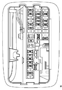
Dodge Avenger (2014) – fuse box diagram

Dodge Avenger (2014) – fuse box diagram

Year of production: 2014

Totally Integrated power module (TIPM)

Cavity Cartridge fuse Mini fuse Description
1 40 Power Top Module – If Equipped
2 20 Brake Vacuum Pump
3 10 Center High Mounted Stop Light (CHMSL)/Brake Switch
4 10 Ignition Switch
5 20 Trailer Tow — If Equipped
6 10 Power Mirror Switch/Climate Controls
7 30 Ignition Off Draw (IOD) Sense 1
8 30 Ignition Off Draw (IOD) Sense 2
9 40 Battery Feed – Power Seats – If Equipped
10 20 Instrument Panel/Power Locks/Interior Lights
11 15 Selectable Power Outlet (Inside Center Arm Rest)
12 20 Spare
13 20 Ignition/Cigar Lighter
14 10 Instrument Panel
15 40 Radiator Fan Relay
16 15 Sunroof – If Equipped
17 10 Wireless Control Module (WCM)/Clock/Steering Control Module (SCM)
18 40 Auto Shutdown (ASD) Relay
19 20 Audio Amplifier – If Equipped
20 15 Radio
21 10 Siren – If Equipped
22 10 Ignition Run — Climate Controls/Hot Cupholder – if equipped
23 15 Auto Shutdown (ASD) Relay Feed 3
24 25 Sunroof – If Equipped
25 10 Ignition Run — Heated Mirrors – If Equipped
26 15 Auto Shutdown (ASD) Relay Feed 2
27 10 Ignition Run – Occupant Classification Module (OCM)/Occupant Restraint Controller (ORC)
28 10 Ignition Run — Occupant Classification Module (OCM)/Occupant Restraint Controller (ORC)
29 Hot Car (No Fuse Required)
30 20 Ignition Run — Heated Seats – If Equipped
31 Spare
32 30 Auto Shutdown (ASD) Relay Feed 1
33 10 Switch Bank/Diagnostic Link Connector/Powertrain Control Module (PCM)
34 30 Anti-Lock Brakes (ABS) Module – If Equipped/Electronic Stability Control (ESC) Module – If Equipped
35 40 Anti-Lock Brakes (ABS) Module – If Equipped/Electronic Stability Control (ESC) Module – If Equipped
36 30 Passenger Door Module (PDM)/Driver Door Module (DDM)
37 25 Power Top Module – If Equipped

WARNING: Terminal and harness assignments for individual connectors will vary depending on vehicle equipment level, model, and market.

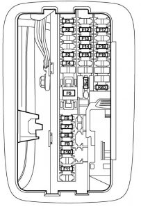
Dodge Avenger (2013) – fuse box diagram

Dodge Avenger (2013) – fuse box diagram

Year of production: 2013

Totally Integrated power module (TIPM)

Cavity Cartridge fuse Mini fuse Description
1 40 Power Top Module – If Equipped
2 20 Brake Vacuum Pump
3 10 Center High Mounted Stop Light (CHMSL)/Brake Switch
4 10 Ignition Switch
5 20 Trailer Tow — If Equipped
6 10 Power Mirror Switch/Climate Controls
7 30 Ignition Off Draw (IOD) Sense 1
8 30 Ignition Off Draw (IOD) Sense 2
9 40 Battery Feed – Power Seats – If Equipped
10 20 Instrument Panel/Power Locks/Interior Lights
11 15 Selectable Power Outlet (Inside Center Arm Rest)
12 20
13 20 Ignition/Cigar Lighter
14 10 Instrument Panel
15 40 Radiator Fan Relay
16 15 Sunroof – If Equipped
17 10 Wireless Control Module (WCM)/Clock/Steering Control Module (SCM)
18 40 Auto Shutdown (ASD) Relay
19 20 Audio Amplifier – If Equipped
20 15 Radio
21 10 Siren – If Equipped
22 10 Ignition Run — Climate Controls/Hot Cupholder – if equipped
23 15 Auto Shutdown (ASD) Relay Feed 3
24 25 Sunroof – If Equipped
25 10 Ignition Run — Heated Mirrors – If Equipped
26 15 Auto Shutdown (ASD) Relay Feed 2
27 10 Ignition Run – Occupant Classification Module (OCM)/Occupant Restraint Controller (ORC)
28 10 Ignition Run — Occupant Classification Module (OCM)/Occupant Restraint Controller (ORC)
29 Hot Car (No Fuse Required)
30 20 Ignition Run — Heated Seats – If Equipped
31 Spare
32 30 Auto Shutdown (ASD) Relay Feed 1
33 10 Switch Bank/Diagnostic Link Connector/Powertrain Control Module (PCM)
34 30 Anti-Lock Brakes (ABS) Module – If Equipped/Electronic Stability Control (ESC) Module – If Equipped
35 40 Anti-Lock Brakes (ABS) Module – If Equipped/Electronic Stability Control (ESC) Module – If Equipped
36 30 Passenger Door Module (PDM)/Driver Door Module (DDM)
37 25 Power Top Module – If Equipped

WARNING: Terminal and harness assignments for individual connectors will vary depending on vehicle equipment level, model, and market.

Dodge Avenger (2012) – fuse box diagram

Dodge Avenger (2012) – fuse box diagram

Year of production: 2012

Totally Integrated power module (TIPM)

Cavity Cartridge fuse Mini fuse Description
1 40 Power Top Module – If Equipped
2 20 Brake Vacuum Pump
3 10 Center High Mounted Stop Light (CHMSL)/Brake Switch
4 10 Ignition Switch
5 20 Trailer Tow — If Equipped
6 10 Power Mirror Switch/Climate Controls
7 30 Ignition Off Draw (IOD) Sense 1
8 30 Ignition Off Draw (IOD) Sense 2
9 40 Battery Feed – Power Seats – If Equipped
10 20 Instrument Panel/Power Locks/Interior Lights
11 15 Selectable Power Outlet (Inside Center Arm Rest)
12
13 20 Ignition/Cigar Lighter
14 10 Instrument Panel
15 40 Radiator Fan Relay
16 15 Sunroof – If Equipped
17 10 Wireless Control Module (WCM)/Clock/Steering Control Module (SCM)
18 40 Auto Shutdown (ASD) Relay
19 20 Audio Amplifier – If Equipped
20 15 Radio
21 10 Siren – If Equipped
22 10 Ignition Run — Climate Controls/Hot Cupholder – if equipped
23 15 Auto Shutdown (ASD) Relay Feed 3
24 25 Sunroof – If Equipped
25 10 Ignition Run — Heated Mirrors – If Equipped
26 15 Auto Shutdown (ASD) Relay Feed 2
27 10 Ignition Run – Occupant Classification Module (OCM)/Occupant Restraint Controller (ORC)
28 10 Ignition Run — Occupant Classification Module (OCM)/Occupant Restraint Controller (ORC)
29 Hot Car (No Fuse Required)
30 20 Ignition Run — Heated Seats – If Equipped
31 Spare
32 30 Auto Shutdown (ASD) Relay Feed 1
33 10 Switch Bank/Diagnostic Link Connector/Powertrain Control Module (PCM)
34 30 Anti-Lock Brakes (ABS) Module – If Equipped/Electronic Stability Control (ESC) Module – If Equipped
35 40 Anti-Lock Brakes (ABS) Module – If Equipped/Electronic Stability Control (ESC) Module – If Equipped
36 30 Passenger Door Module (PDM)/Driver Door Module (DDM)
37 25 Power Top Module – If Equipped

WARNING: Terminal and harness assignments for individual connectors will vary depending on vehicle equipment level, model, and market.

Dodge Avenger (2011) – fuse box diagram

Dodge Avenger (2011) – fuse box diagram

Year of production: 2011

Totally Integrated power module (TIPM)

Cavity Cartridge fuse Mini fuse Description
1 40 Power Top Module – If Equipped
2 20 AWD Module
3 10 Battery Feed — Center High Mounted Stop Light (CHMSL)/Brake Switch
4 10 Battery Feed — Ignition Switch
5 20 Trailer Tow — If Equipped
6 10 Ignition Off Draw (IOD) — Power Mirror Switch/Climate Controls
7 30 Ignition Off Draw (IOD) Sense 1
8 30 Ignition Off Draw (IOD) Sense 2
9 40 Battery Feed — Power Seats – if equipped/PZEV Air Pump – if equipped
10 20 Battery Feed — Cabin Compartment Node (CCN)
11 15 Selectable Power Outlet
12 20
13 20 Ignition
14 10 Instrument Panel
15 40 Radiator Fan Relay
16 15 Cigar Lighter/Sunroof – If Equipped
17 10 Wireless Control Module (WCM)/Clock/Steering Control Module (SCM)
18 40 Auto Shutdown (ASD) Relay
19 20 Audio Amplifier – If Equipped
20 15 Radio
21 10 Siren – If Equipped
22 10 Ignition Run — Climate Controls/Hot Cupholder – if equipped
23 15 Auto Shutdown (ASD) Relay Feed 3
24 25 Sunroof – If Equipped
25 10 Ignition Run — Heated Mirrors – If Equipped
26 15 Auto Shutdown (ASD) Relay Feed 2
27 10 Ignition Run – Occupant Classification Module (OCM)/Occupant Restraint Controller (ORC)
28 10 Ignition Run — Occupant Classification Module (OCM)/Occupant Restraint Controller (ORC)
29 Hot Car (No Fuse Required)
30 20 Ignition Run — Heated Seats – If Equipped
31 10 Headlamp Washer – If Equipped
32 30 Auto Shutdown (ASD) Relay Feed 1
33 10 Switch Bank/Diagnostic Link Connector/Powertrain Control Module (PCM)
34 30 Anti-Lock Brakes (ABS) Module – If Equipped/Electronic Stability Control (ESC) Module – If Equipped
35 40 Anti-Lock Brakes (ABS) Module – If Equipped/Electronic Stability Control (ESC) Module – If Equipped
36 30 Passenger Door Module (PDM)/Driver Door Module (DDM)
37 25 Power Top Module – If Equipped

WARNING: Terminal and harness assignments for individual connectors will vary depending on vehicle equipment level, model, and market.

Dodge Avenger (2010) – fuse box diagram

Dodge Avenger (2010) – fuse box diagram

Year of production: 2010

Totally Integrated power module (TIPM)

Cavity Cartridge fuse Mini fuse Description
1 40 Power Top Module – If Equipped
2 20 AWD Module
3 10 Battery Feed — Center High Mounted Stop Light (CHMSL)/Brake Switch
4 10 Battery Feed — Ignition Switch
5 20 Trailer Tow — If Equipped
6 10 Ignition Off Draw (IOD) — Power Mirror Switch/Climate Controls
7 30 Ignition Off Draw (IOD) Sense 1
8 30 Ignition Off Draw (IOD) Sense 2
9 40 Battery Feed — Power Seats – if equipped/PZEV Air Pump – if equipped
10 20 Battery Feed — Cabin Compartment Node (CCN)
11 15 Selectable Power Outlet
12 20
13 20
14 10 Ignition Off Draw (IOD) — Cabin Compartment Node (CCN)/ Interior Lighting
15 40 Battery Feed — Radiator Fan Relay
16 15 IGN Run/ACC — Cigar Lighter/PWR Sunroof Mod
17 10 Ignition Off Draw (IOD) — Wireless Control Module (WCM)/Clock/Steering Control Module (SCM)
18 40 Battery Feed — Auto Shutdown (ASD) Relay
19 20 Ignition Off Draw (IOD) — Power Amp Feed 2 – if equipped
20 15 Ignition Off Draw (IOD) — Radio
21 10
22 10 Ignition Run — Climate Controls/Hot Cupholder – if equipped
23 15 Auto Shutdown (ASD) Relay Feed 3
24 25 Battery Feed — PWR Sunroof Feed
25 10 Ignition Run — Heated Mirrors – If Equipped
26 15 Auto Shutdown (ASD) Relay Feed 2
27 10 Ignition Run — Occupant Classification Module (OCM)/Occupant Restraint Controller (ORC)
28 10 Ignition Run — Occupant Classification Module (OCM)/Occupant Restraint Controller (ORC)
29 Hot Car (No Fuse Required)
30 20 Ignition Run — Heated Seats – If Equipped
31 10
32 30 Auto Shutdown (ASD) Relay Feed 1
33 10 Battery Feed — Switch Bank/Diagnostic Link Connector/Powertrain Control Module (PCM)
34 30 Battery Feed — Anti-Lock Brakes (ABS) Module – if equipped/Electronic Stability Program (ESP) Module – If Equipped
35 40 Battery Feed — Anti-Lock Brakes (ABS) Module – If Equipped/Electronic Stability Program (ESP) Module – If Equipped
36 30 Battery Feed — Passenger Door Module (PDM)/Driver Door Module (DDM)
37 25 Power Top Module – If Equipped

WARNING: Terminal and harness assignments for individual connectors will vary depending on vehicle equipment level, model, and market.

Dodge Avenger (2008 – 2009) – fuse box diagram

Dodge Avenger (2008 – 2009) – fuse box diagram

Year of production: 2008, 2009

Totally Integrated power module (TIPM)

Cavity Cartridge fuse Mini fuse Description
1 40
2 20
3 10 Battery Feed — Center High Mounted Stop Light (CHMSL)/Brake Switch
4 10 Battery Feed — Ignition Switch
5 20 Trailer Tow — If Equipped
6 10 Ignition Off Draw (IOD) — Power Mirror Switch/Climate Controls
7 30 Ignition Off Draw (IOD) Sense 1
8 30 Ignition Off Draw (IOD) Sense 2
9 40 Battery Feed — Power Seats – if equipped/PZEV Air Pump – if equipped
10 20 Battery Feed — Cabin Compartment Node (CCN)
11 15 Selectable Power Outlet
12 20
13 20
14 10 Ignition Off Draw (IOD) — Cabin Compartment Node (CCN)/ Interior Lighting
15 40 Battery Feed — Radiator Fan Relay
16 15 IGN Run/ACC — Cigar Lighter/PWR Sunroof Mod
17 10 Ignition Off Draw (IOD) — Wireless Control Module (WCM)/Clock/Steering Control Module (SCM)
18 40 Battery Feed — Auto Shutdown (ASD) Relay
19 20 Ignition Off Draw (IOD) — Power Amp Feed 2 – if equipped
20 15 Ignition Off Draw (IOD) — Radio
21 10
22 10 Ignition Run — Climate Controls/Hot Cupholder – if equipped
23 15 Auto Shutdown (ASD) Relay Feed 3
24 25 Battery Feed — PWR Sunroof Feed
25 10 Ignition Run — Heated Mirrors – If Equipped
26 15 Auto Shutdown (ASD) Relay Feed 2
27 10 Ignition Run — Occupant Classification Module (OCM)/Occupant Restraint Controller (ORC)
28 10 Ignition Run — Occupant Classification Module (OCM)/Occupant Restraint Controller (ORC)
29 Hot Car (No Fuse Required)
30 20 Ignition Run — Heated Seats – If Equipped
31 10
32 30 Auto Shutdown (ASD) Relay Feed 1
33 10 Battery Feed — Switch Bank/Diagnostic Link Connector/Powertrain Control Module (PCM)
34 30 Battery Feed — Anti-Lock Brakes (ABS) Module – if equipped/Electronic Stability Program (ESP) Module – If Equipped
35 40 Battery Feed — Anti-Lock Brakes (ABS) Module – If Equipped/Electronic Stability Program (ESP) Module – If Equipped
36 30 Battery Feed — Passenger Door Module (PDM)/Driver Door Module (DDM)
37 25

WARNING: Terminal and harness assignments for individual connectors will vary depending on vehicle equipment level, model, and market.

Dodge 5500 (2008 – 2009) – fuse box diagram

Dodge 5500 (2008 – 2009) – fuse box diagram

Year of production: 2008, 2009

Integrated power module

Cavity Cartridge fuse Mini fuse Description
1 20 Power Outlet Console
2 20 Cabin Compartment Node (CCN) Door Locks
3
4 15 Aisin Transmission Controls (Diesel Only)
5 20 Power Sunroof
6 10 Vistronic Fan/Wastegate Solenoid
7
8 10 Heated Mirrors
9 30 Off Road Module Power
10 5 Trx-Off Rd Pkg Sen (Gas Engine Only) NOTE: Insert 5 amp
fuse in this cavity to enable the TRX capability (If Equipped).
11 20 Ignition Off Draw (IOD)-Cabin Compartment Node
(CCN)/Radio/Under Hood Lamp/Wireless Control Module
(WCM)/Satellite Digital Audio Receiver (SDARS)/Hands Free Module (HFM)/EOM
12 30 Electric Brake
13 25 Power-Battery RWAL/ABS Module Feed
14 15 Park Lights Left
15 20 Trailer Park Lights
16 15 Park Lights Right
17
18 40 ABS Pump
19 30 Trailer Tow Battery Feed
20 10 Occupant Restraints Controller (ORC) 2
21 10 Occupant Restraints/Pass Disable Switch
22 2 IGN Switch Feed
23 10 HVAC
24 20 AISIN Relay Feed (Diesel Only)
25 10 Power Mirror/T-Case Brake
26 20 Brake Switch/Center High Mount Stop Light (CHMSL)/Aftermarket CHMSL
27 40 Power Seats
28 10 Power Run/Start-PCM/Steering Angle Sensor
29 10 4X4 Switch/Pass Dr Switch/EC Mirror
30 15 Power Run/Start-ABS/RWAL/Smart Bar/YAW Sensor/ Universal Exhaust Gas Oxygen (Uego) Sensor Controller
31 10 PCM (Gas)/TCM (Diesel 58RFE)
32 10 Power Ignition Run — Adjustable Pedals LED
33 10 Power-IGN Run — HVAC
34
35 15 Cabin Compartment Node (CCN) Illumination
36 25 Audio_Amplifier
37 15 Variable Gate Turbo (VGT) — Turbo Diesel
38 20 Power Outlet IP
39 10 Seatbelt Tension Reducer/Power IGN Run/Acc
40 20 Power IGN Run/Acc — Cigar Lighter/Rear Power Point
41
42 30 Diesel PCM (Diesel Only)

WARNING: Terminal and harness assignments for individual connectors will vary depending on vehicle equipment level, model, and market.

Dodge 4500 (2008 – 2009) – fuse box diagram

Dodge 4500 (2008 – 2009) – fuse box diagram

Year of production: 2008, 2009

Integrated power module

Cavity Cartridge fuse Mini fuse Description
1 20 Power Outlet Console
2 20 Cabin Compartment Node (CCN) Door Locks
3
4 15 Aisin Transmission Controls (Diesel Only)
5 20 Power Sunroof
6 10 Vistronic Fan/Wastegate Solenoid
7
8 10 Heated Mirrors
9 30 Off Road Module Power
10 5 Trx-Off Rd Pkg Sen (Gas Engine Only) NOTE: Insert 5 amp
fuse in this cavity to enable the TRX capability (If Equipped).
11 20 Ignition Off Draw (IOD)-Cabin Compartment Node
(CCN)/Radio/Under Hood Lamp/Wireless Control Module
(WCM)/Satellite Digital Audio Receiver (SDARS)/Hands Free Module (HFM)/EOM
12 30 Electric Brake
13 25 Power-Battery RWAL/ABS Module Feed
14 15 Park Lights Left
15 20 Trailer Park Lights
16 15 Park Lights Right
17
18 40 ABS Pump
19 30 Trailer Tow Battery Feed
20 10 Occupant Restraints Controller (ORC) 2
21 10 Occupant Restraints/Pass Disable Switch
22 2 IGN Switch Feed
23 10 HVAC
24 20 AISIN Relay Feed (Diesel Only)
25 10 Power Mirror/T-Case Brake
26 20 Brake Switch/Center High Mount Stop Light (CHMSL)/Aftermarket CHMSL
27 40 Power Seats
28 10 Power Run/Start-PCM/Steering Angle Sensor
29 10 4X4 Switch/Pass Dr Switch/EC Mirror
30 15 Power Run/Start-ABS/RWAL/Smart Bar/YAW Sensor/ Universal Exhaust Gas Oxygen (Uego) Sensor Controller
31 10 PCM (Gas)/TCM (Diesel 58RFE)
32 10 Power Ignition Run — Adjustable Pedals LED
33 10 Power-IGN Run — HVAC
34
35 15 Cabin Compartment Node (CCN) Illumination
36 25 Audio_Amplifier
37 15 Variable Gate Turbo (VGT) — Turbo Diesel
38 20 Power Outlet IP
39 10 Seatbelt Tension Reducer/Power IGN Run/Acc
40 20 Power IGN Run/Acc — Cigar Lighter/Rear Power Point
41
42 30 Diesel PCM (Diesel Only)

WARNING: Terminal and harness assignments for individual connectors will vary depending on vehicle equipment level, model, and market.

Dodge 3500 (2007) – fuse box diagram

Dodge 3500 (2007) – fuse box diagram

Year of production: 2007

Integrated power module

Cavity Cartridge fuse Mini fuse Description
1 20 Power Outlet Console
2 20 Cabin Compartment Node (CCN) Door Locks
3
4 20 Aisin Transmission Controls (Diesel Only)
5 20 Power Sunroof
6 10 Vistronic Fan/Wastegate Solenoid
7
8 10 Heated Mirrors
9 30 Off Road Module Power
10 5 Trx-Off Rd Pkg Sen (Gas Engine Only) NOTE: Insert 5 amp fuse in this cavity to enable the TRX capability (If Equipped).
11 20 Ignition Off Draw (IOD)-Cabin Compartment Node
(CCN)/Radio/Under Hood Lamp/Wireless Control Module
(WCM)/Satellite Digital Audio Receiver (SDARS)/Hands Free Module (HFM)/EOM
12 30 Electric Brake
13 25 Power-Battery RWAL/ABS Module Feed
14 15 Park Lights Left
15 20 Trailer Park Lights
16 15 Park Lights Right
17
18 40 ABS Pump
19 30 Trailer Tow Battery Feed
20 10 Occupant Restraints Controller (ORC) 2
21 10 Occupant Restraints/Pass Disable Switch
22 2 IGN Switch Feed
23 10 HVAC
24 20 AISIN Relay Feed (Diesel Only)
25 10 Power Mirror/T-Case Brake
26 20 Brake Switch/Center High Mount Stop Light (CHMSL)/Aftermarket CHMSL
27 40 Power Seats
28 10 Power Run/Start-PCM/Steering Angle Sensor
29 10 4X4 Switch/Pass Dr Switch/EC Mirror
30 15 Power Run/Start-ABS/RWAL/Smart Bar/YAW Sensor/ Universal Exhaust Gas Oxygen (Uego) Sensor Controller
31 10 PCM (Gas)/TCM (Diesel 58RFE)
32 10 Power Ignition Run — Adjustable Pedals LED
33 10 Power-IGN Run — HVAC
34
35 15 Cabin Compartment Node (CCN) Illumination
36 25 Audio_Amplifier
37 15 Variable Gate Turbo (VGT) — Turbo Diesel
38 20 Power Outlet IP
39 10 Seatbelt Tension Reducer/Power IGN Run/Acc
40 20 Power IGN Run/Acc — Cigar Lighter/Rear Power Point
41
42 30 Diesel PCM (Diesel Only)

WARNING: Terminal and harness assignments for individual connectors will vary depending on vehicle equipment level, model, and market.

Dodge 2500 (2007) – fuse box diagram

Dodge 2500 (2007) – fuse box diagram

Year of production: 2007

Integrated power module

Cavity Cartridge fuse Mini fuse Description
1 20 Power Outlet Console
2 20 Cabin Compartment Node (CCN) Door Locks/Brake Transmission Shift Interlock (BTSI)
3 20 Spare
4 20 Spare
5 20 Power Sunroof
6 10 Occupant Classification Module (OCM)/VIST Fan/Wastegate
7 15 Reverse Lockout Solenoid Battery (SRT-10 Only)
8 10 Heated Mirrors
9 30 Off Road Module Power
10 5 Trx-Off Rd Pkg Sen (Gas Engine Only)
11 20 Ignition Off Draw (IOD)-Cabin Compartment Node (CCN)/Radio/Under Hood Lamp/Wireless Control Module
(WCM)/Satellite Digital Audio Receiver (SDARS)/Hands Free Module (HFM)
12 30 Electric Brake
13 25 Power-Battery RWAL/ABS Module Feed
14 15 Park Lamps Left
15 20 Trailer Park Lamps
16 15 Park Lamps Right
17 15 Spare
18 40 ABS Pump
19 30 Trailer Tow
20 10 Occupant Restraints Controller (ORC) 2
21 10 Occupant Restraints Controller (ORC) Preset Carrier
22 2 IGN Switch Feed
23 10 Engine Control Module (ECM)/Wireless Control Module (WCM)/HVC
24 20 Subwoofer Amplifier (SRT-10 Only)
25 10 Power Mirror
26 20 Brake Switch/Center High Mount Stop Lamp (CHMSL)
27 40 Power Seats
28 10 Power Run/Start-NCC/Wireless Control Module (WCM)/ ABS/RWAL
29 10 Switches/EC Mirror/Smart Bar
30 15 Spare
31 10 PCM/Transfer Case Brake
32 10 HVAC/Ajustable Pedals/Heated Seats Switch LED/Exhaust Brake
33 10 Power-IGN Run Misc
34 10 Spare
35 15 Cabin Compartment Node (CCN) Illumination
36 25 Audio_Amplifier
37 15 Spare
38 20 Power Outlet IP
39 10 Sunroof/Seatbelt Tensioner
40 20 Cigar Lighter
41 25 Spare
42 30 Diesel PCM (Diesel Only)

WARNING: Terminal and harness assignments for individual connectors will vary depending on vehicle equipment level, model, and market.