Subaru Legacy (2008) – fuse box diagram
Year of production: 2008
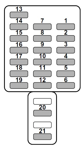
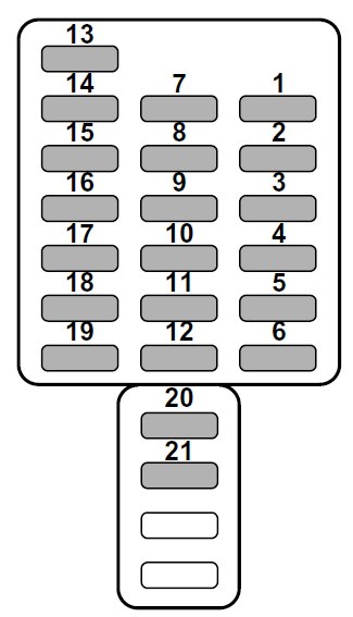
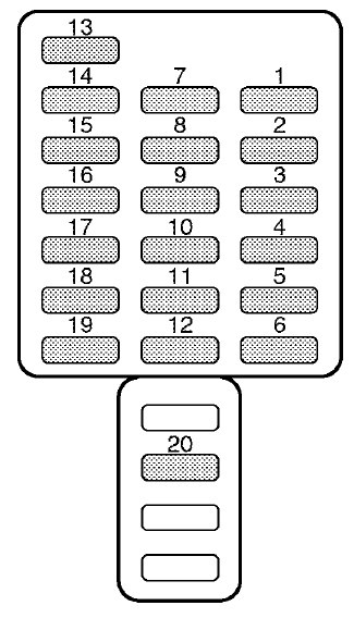
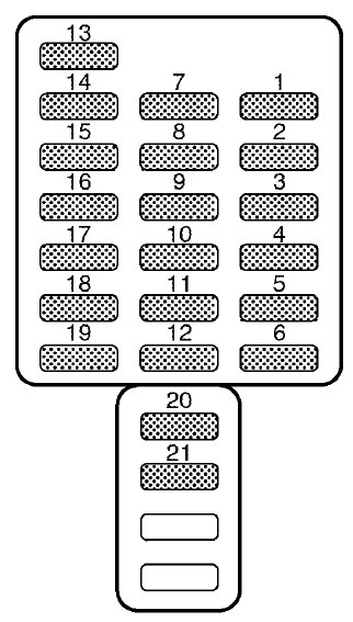
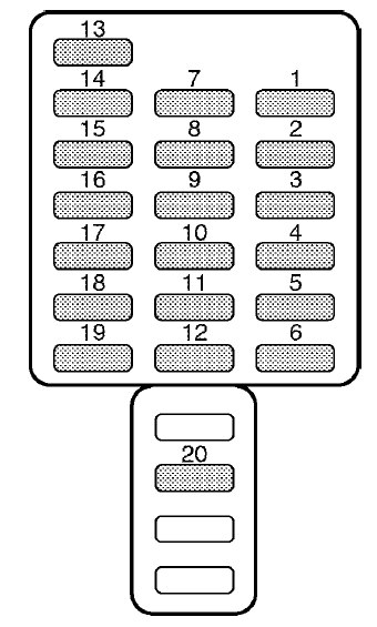
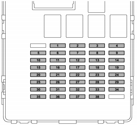
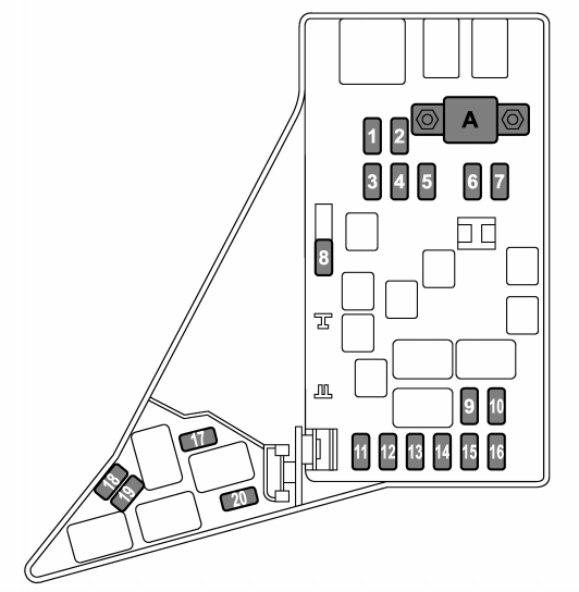
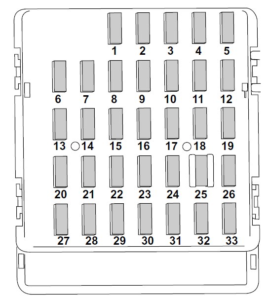
Fuse panel located in the passenger compartment
| Fuse | Ampere rating [A] | Circuit |
| 1 | 20 | Cargo fan, Trailer hitch connector |
| 2 | — | — |
| 3 | 15 | Door locking |
| 4 | 15 | Front wiper deicer relay, Moonroof |
| 5 | 15 | Combination meter |
| 6 | 7,5 | Remote control rear view mirrors, Seat heater relay, Vanity mirror light |
| 7 | 15 | Combination meter, Integrated unit |
| 8 | 20 | Stop light |
| 9 | 20 | Mirror heater, Front wiper deicer |
| 10 | 7,5 | Power supply (Battery) |
| 11 | 7,5 | Turn signal unit, Clock |
| 12 | 15 | Automatic transmission unit, Engine control unit, Integrated unit |
| 13 | 20 | Cargo socket |
| 14 | 15 | Position light, Tail light, Rear combination light |
| 15 | — | — |
| 16 | 10 | Illumination |
| 17 | 15 | Seat heaters |
| 18 | 10 | Back-up light |
| 19 | 7,5 | Headlight right side relay |
| 20 | 10 | Cigarette lighter socket |
| 21 | 7,5 | Starter relay |
| 22 | 15 | Air conditioner, Rear window defogger relay coil |
| 23 | 15 | Rear wiper, Rear window washer |
| 24 | 15 | Audio unit, Clock |
| 25 | 15 | SRS airbag system |
| 26 | 7,5 | Power window relay |
| 27 | 15 | Blower fan |
| 28 | 15 | Blower fan |
| 29 | 15 | Fog light |
| 30 | 30 | Front wiper, Front wiper washer |
| 31 | 7,5 | Auto air conditioner unit, Integrated unit |
| 32 | 7,5 | Headlight left side relay |
| 33 | 7,5 | ABS/Vehicle dynamics control unit |
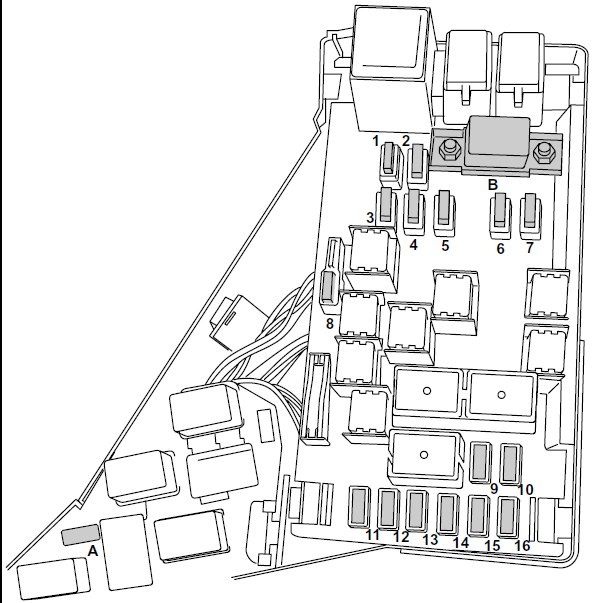
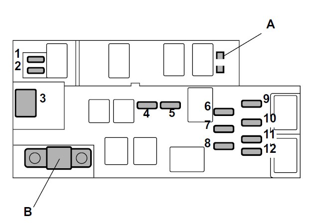
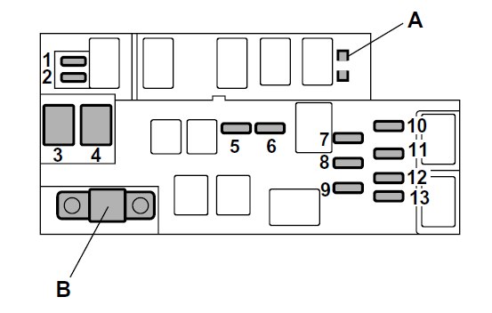
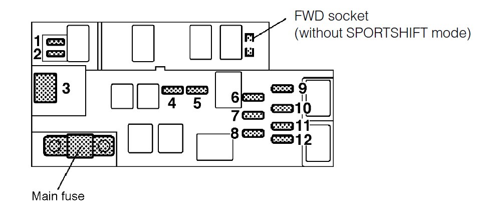
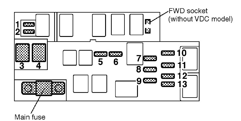
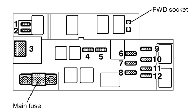
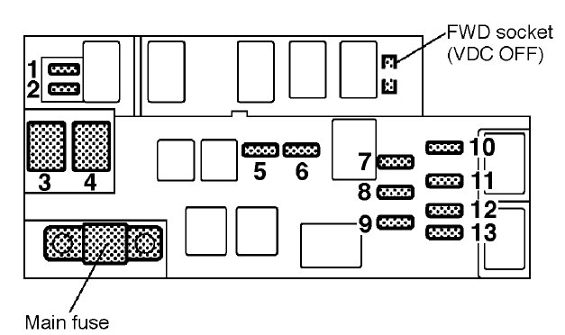
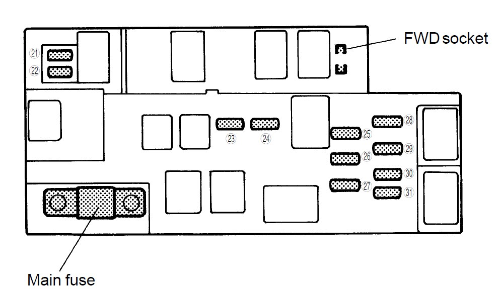
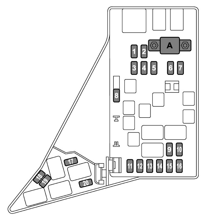
Fuse panel located in the engine compartment
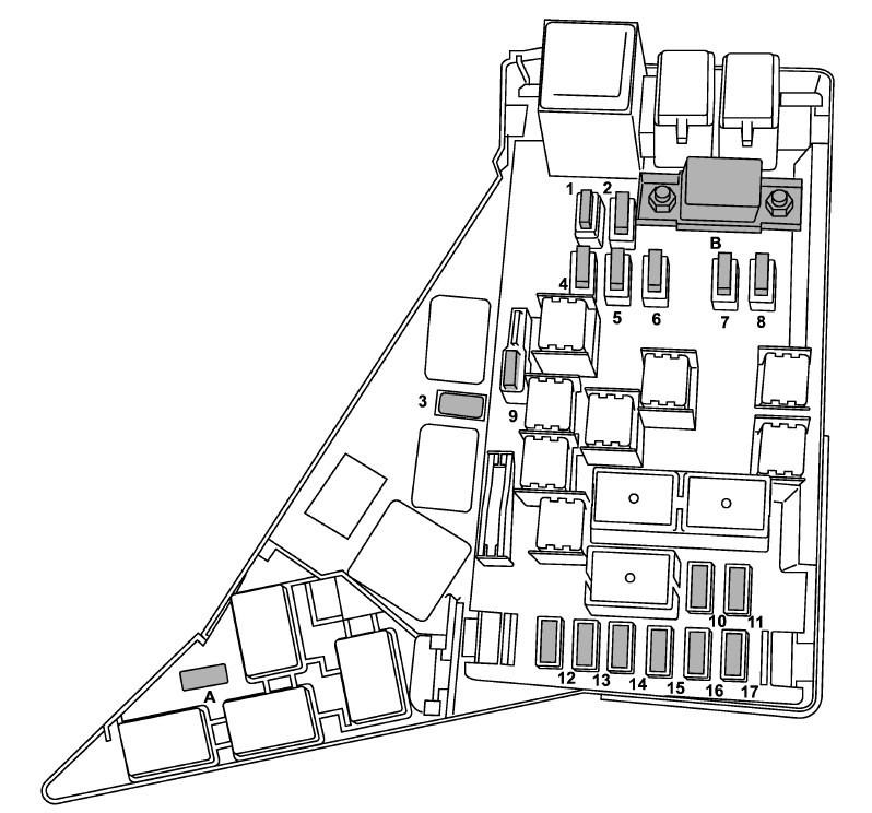
engine compartment
| Fuse | Ampere rating [A] | Power consumer |
| 1 | 30 | ABS unit, Vehicle dynamics control unit |
| 2 | 25 | Main fan (3.0-liter models) |
| 3 | 10 | Secondary air combination valve (Turbo models) |
| 4 | 25 | Sub fan (Except 3.0-liter models) |
| 5 | 25 | Main fan |
| 6 | 20 | Audio |
| 7 | 15 | Headlight (right side) |
| 8 | 15 | Headlight (left side) |
| 9 | 20 | Back-up light |
| 10 | 15 | Horn |
| 11 | 25 | Rear window defogger |
| 12 | 15 | Fuel pump |
| 13 | 15 | Automatic transmission control unit |
| 14 | 7,5 | Engine control unit |
| 15 | 15 | Turn and hazard warning flasher |
| 16 | 20 | Parking switch |
| 17 | 7,5 | Alternator |
| A | FWD socket (AT vehicles – except Turbo models and 3.0-liter models) | |
| B | Main fuse |
WARNING: Terminal and harness assignments for individual connectors will vary depending on vehicle equipment level, model, and market.