Holden Barina Spark (MJ; 2011 – 2015) – fuse box diagram
Year of production: 2011, 2012, 2013, 2014, 2015
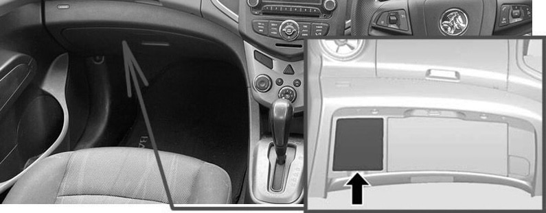
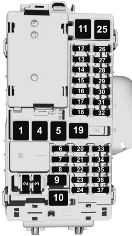
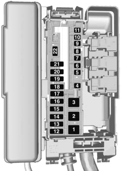
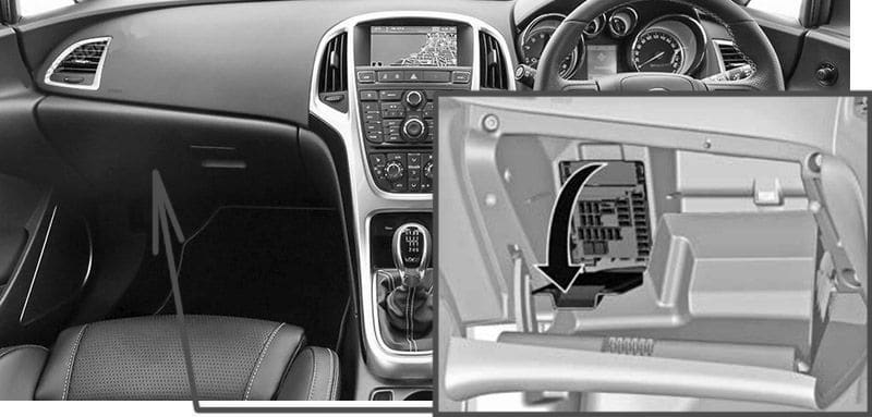
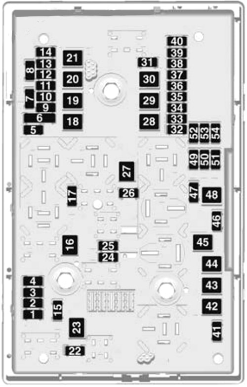
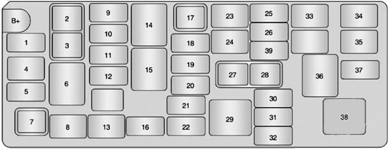
Passenger Compartment Fuse Box
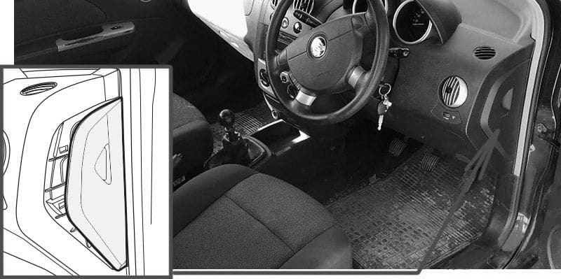
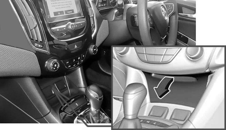
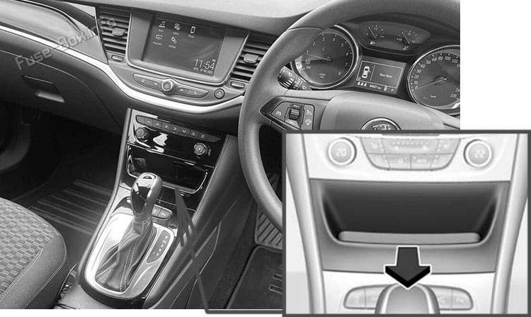
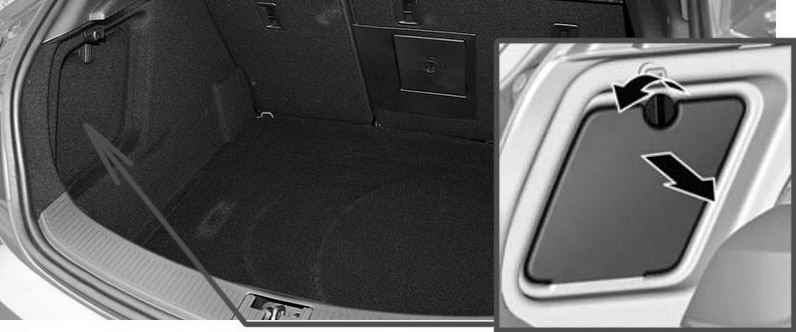
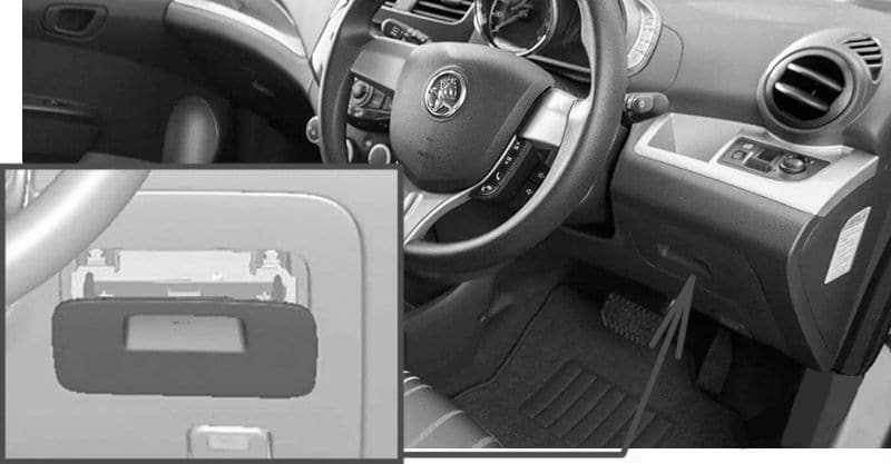
Fuse Box Location
The interior fuse box is located on the underside of the driver side of the instrument panel (there may be a lid or not).
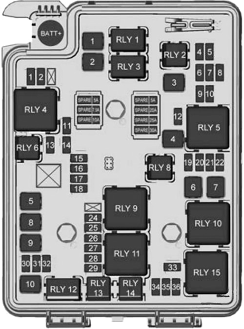
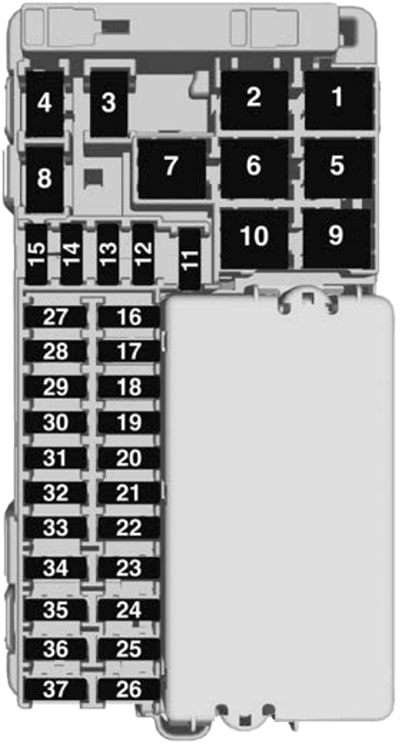
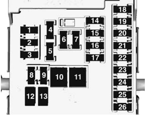
Fuse Box Diagram
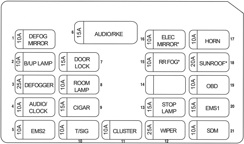
Version 1 (Automatic transmission)
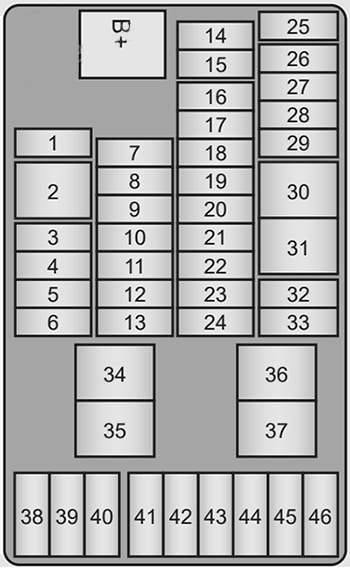
| № | Function |
|---|---|
| 1 | – |
| 2 | – |
| 3 | Heating ventilation and air conditioning switch |
| 4 | – |
| 5 | – |
| 6 | Blower |
| 7 | Body control module 4 |
| 8 | Body control module 5 |
| 9 | Body control module 7 |
| 10 | Instrument panel cluster |
| 11 | – |
| 12 | Air bag power |
| 13 | – |
| 14 | SWC BKLT |
| 15 | |
| 16 | Body control module 1 |
| 17 | Body control module 2 |
| 18 | Body control module 3 |
| 19 | Body control module 6 |
| 20 | Body control module 8 |
| 21 | – |
| 22 | Data link connection |
| 23 | Discrete logic ignition sensor |
| 24 | Outside rear view mirror |
| 25 | – |
| 26 | – |
| 27 | – |
| 28 | Instrument panel cluster |
| 29 | Air bag ignition |
| 30 | – |
| 31 | Front window |
| 32 | Auxiliary power outlet |
| 33 | – |
| 34 | Run relay |
| 35 | Logic mode relay |
| 36 | Accessory/retained accessory power relay |
| 37 | – |
| 38 | Radio |
| 39 | Heating ventilation and air conditioning |
| 40 | – |
| 41 | Spare fuse |
| 42 | Spare fuse |
| 43 | Spare fuse |
| 44 | Spare fuse |
| 45 | Spare fuse |
| 46 | Spare fuse |
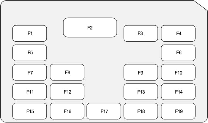
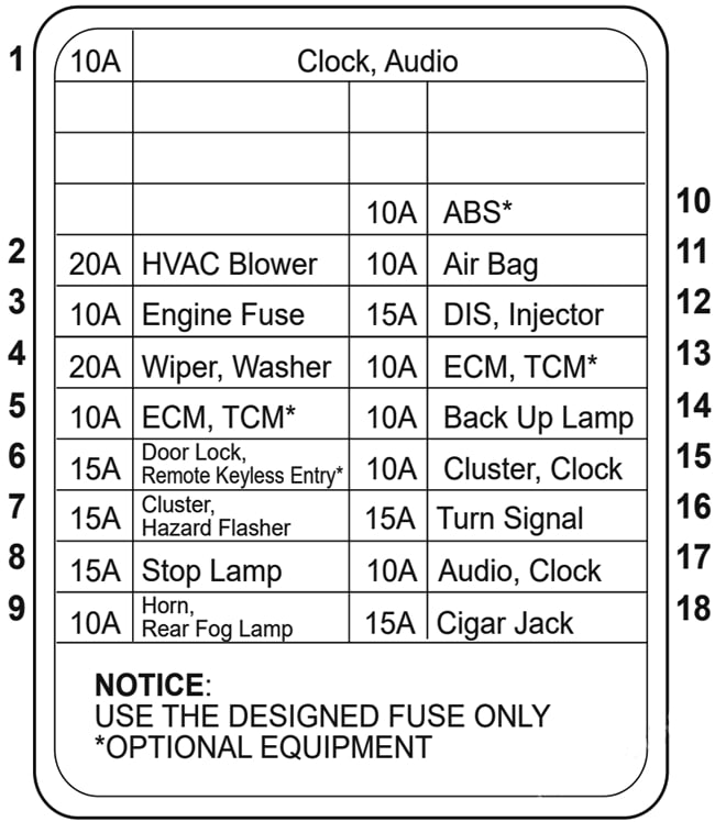
Version 2 (Manual transmission)
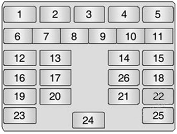
| № | Function |
|---|---|
| 1 | Rear wiper |
| 2 | Mirror / outside rear view mirror |
| 3 | Headlamp |
| 4 | Electric outside rear view mirror |
| 5 | Door lock |
| 6 | Front wiper |
| 7 | Spare fuse |
| 8 | Reverse lamps |
| 9 | Turn signals |
| 10 | Rear demister |
| 11 | 2014-2015: Rear lamps |
| 12 | Instrument panel |
| 13 | Blower |
| 14 | Airbag |
| 15 | Theft deterrent / data link connector |
| 16 | – |
| 17 | 2011-2013: Rear power windows |
| 18 | Radio / remote keyless entry / remote entry |
| 19 | Engine control module (ECM) / theft deterrent |
| 20 | 2011-2013: Front power windows 2014-2015: Heat mat |
| 21 | Power socket / Cigarette lighter |
| 22 | Stop lamps |
| 23 | Starter |
| 24 | Radio / clock / remote keyless entry |
| 25 | 2011-2013: Instrument panel / interior lamps 2014-2015: Airbag |
| 26 | 2014-2015: Interior lamps |
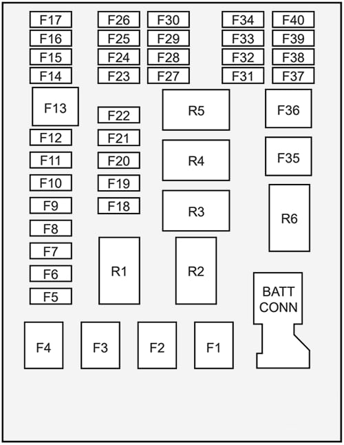
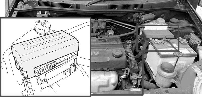
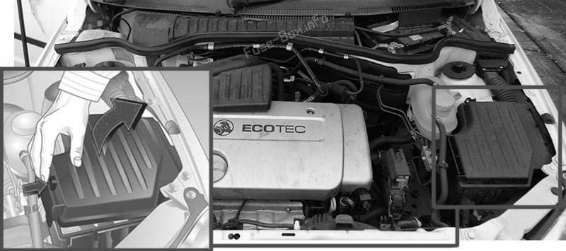
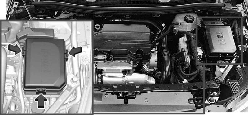
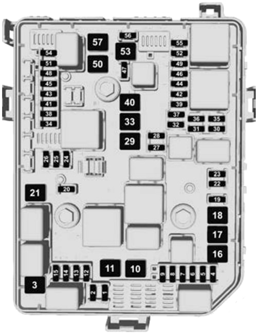
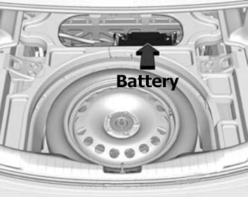
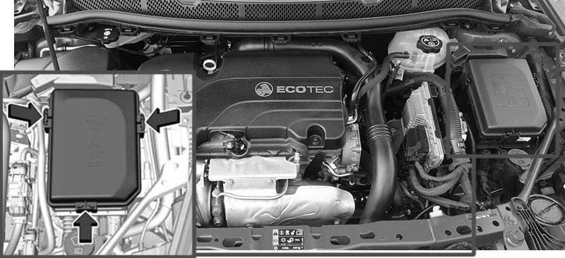
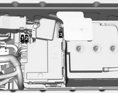
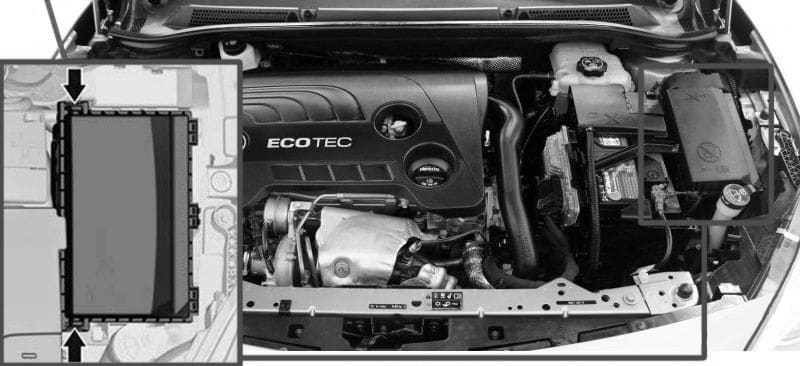
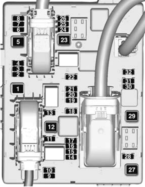
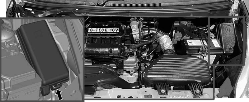
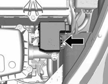
Engine Compartment Fuse Box
Fuse Box Location
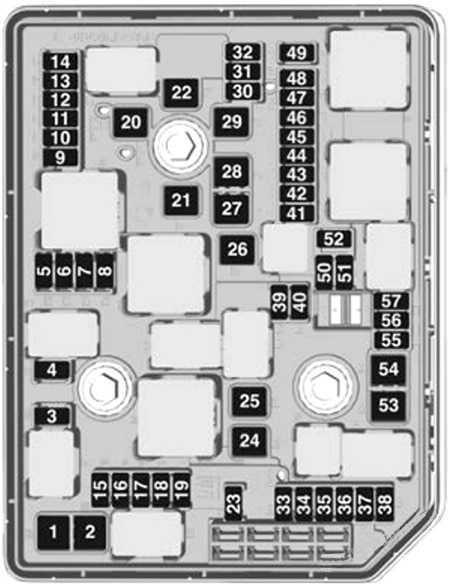
Fuse Box Diagram
Version 1 (Automatic transmission)
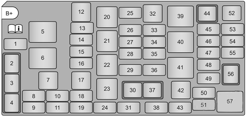
| № | Function |
|---|---|
| 1 | Windscreen washer |
| 2 | Rear Windscreen washer relay |
| 3 | Front Windscreen washer relay |
| 4 | Horn relay |
| 5 | Fan high relay |
| 6 | Fan low relay |
| 7 | ABS1 |
| 8 | Horn |
| 9 | – |
| 10 | – |
| 11 | Spare fuse |
| 12 | Fan high |
| 13 | Front fog |
| 14 | Headlamp high left |
| 15 | Headlamp high right |
| 16 | Fan low |
| 17 | ABS2 |
| 18 | TCM |
| 19 | Spare fuse |
| 20 | Front fog relay |
| 21 | Headlamp high relay |
| 22 | Fuel pump relay |
| 23 | TCM relay |
| 24 | Spare fuse |
| 25 | ABS3 |
| 26 | EMIS2 |
| 27 | Canister |
| 28 | Fuel pump |
| 29 | Front wiper |
| 30 | Front wiper control relay |
| 31 | Spare fuse |
| 32 | Starter |
| 33 | Ignition |
| 34 | EMIS1 |
| 35 | – |
| 36 | – |
| 37 | Front wiper speed relay |
| 38 | – |
| 39 | Starter relay |
| 40 | Engine relay |
| 41 | Run/crank relay |
| 42 | Interior electrical centre |
| 43 | – |
| 44 | Air conditioner relay |
| 45 | Air conditioner |
| 46 | ECM/TCM1 |
| 47 | ECM/TCM2 |
| 48 | Low vacuum switch |
| 49 | AOS |
| 50 | Mirror heater |
| 51 | Rear defog |
| 52 | Fuse puller |
| 53 | TCM relay coil |
| 54 | Voltage sensing |
| 55 | Rear wiper |
| 56 | Rear wiper relay |
| 57 | Rear defog relay |
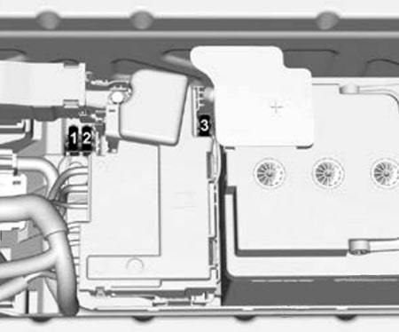
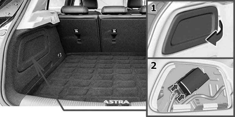
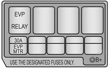
Auxiliary fuse box
| № | Function |
|---|---|
| 1 | EVP relay |
| 2 | – |
| 3 | – |
| 4 | – |
| 5 | EVP motor |
| 6 | – |
| 7 | – |
| 8 | – |
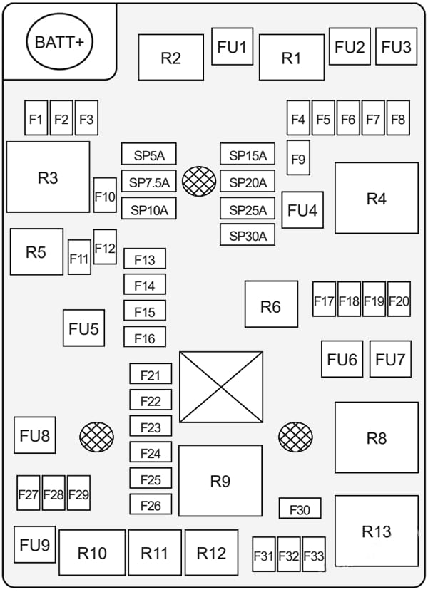
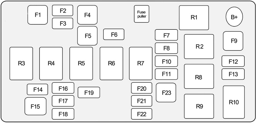
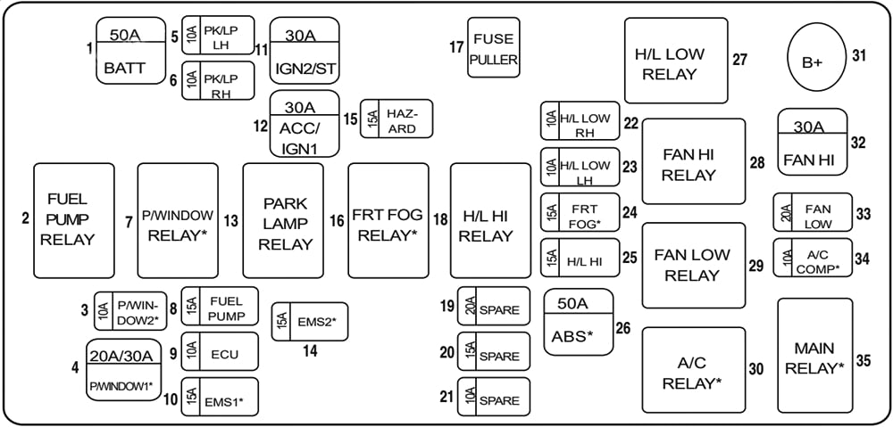
Version 2 (Manual transmission)
| № | Function |
|---|---|
| 1 | Fuel pump |
| 2 | Park relay |
| 3 | Fan low relay |
| 4 | Fan high |
| 5 | Air conditioning |
| 6 | Fan high relay |
| 7 | Air conditioning relay |
| 8 | ABS2 |
| 9 | Park LH |
| 10 | Park RH |
| 11 | Front foq |
| 12 | Fan low |
| 13 | ABS1 |
| 14 | Front fog relay |
| 15 | Fuel pump relay |
| 16 | Spare fuse |
| 17 | Headlamp high relay |
| 18 | Headlamp high |
| 19 | Headlamp low LH |
| 20 | Headlamp low RH |
| 21 | Spare fuse |
| 22 | Spare fuse |
| 23 | lgnition2/starter |
| 24 | Ignition 1 /accessory |
| 25 | Hazard lamps |
| 26 | Horn |
| 27 | Headlamp low relay |
| 28 | Horn relay |
| 29 | Engine main relay |
| 30 | Ignition |
| 31 | EMIS1 |
| 32 | EMIS2 |
| 33 | Instrument panel battery |
| 34 | – |
| 35 | 2014-2015: Front window |
| 36 | 2014-2015: Front window relay |
| 37 | Engine control unit |
| 38 | 2014-2015: Evap relay |
WARNING: Terminal and harness assignments for individual connectors will vary depending on vehicle equipment level, model, and market.