Acura ILX (from 2013) – fuse box diagram
Year of production: 2013, 2014, 2015, 2016, 2017
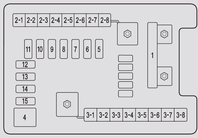
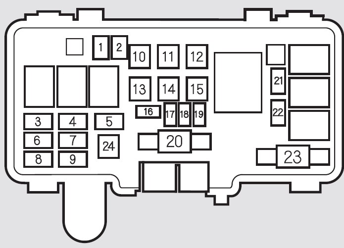
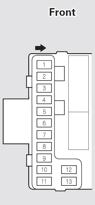
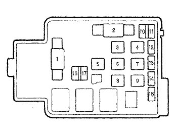
Fuse box in engine compartment
| Fuse |
Circuit protected |
Ampere rating [A] |
| 1 |
EPS |
70 |
| Booster Motor |
40 |
| ABS/VSA Motor |
30 |
| ABS/VSA FSR |
30 |
| WIPER |
30 |
| MAIN Fuse |
100 |
| 2 |
IG MAin |
50 |
| Fuse Box Main |
60 |
| Fuse Box Main 2 |
60 |
| Headlight Main |
30 |
| ST/MG SW*1 |
30 |
| Rear Defogger |
30 |
| — |
— |
| Blower |
40 |
| — |
— |
| Sub Fan Motor |
20 |
| 3 |
— |
— |
| 4 |
IG Coil 2 |
15 |
| 5 |
Starter DIAG, ST MG |
7,5 |
| 6 |
IG Coil 1 |
15 |
| 7 |
— |
— |
| 8 |
— |
— |
| 9 |
— |
— |
| 10 |
— |
— |
| 11 |
Oil Level |
7,5 |
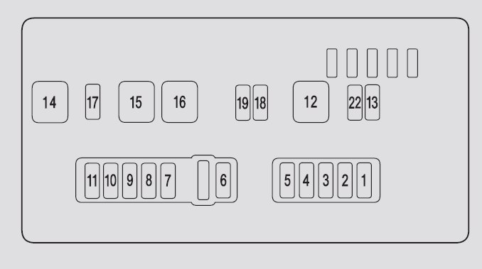
| 12 |
Fog lights |
20 |
| 13 |
IMA1 |
7,5 |
| 14 |
Hazard |
10 |
| 15 |
FI Sub |
15 |
| 16 |
IG Coil |
20 |
| 17 |
Stop |
15 |
| 18 |
Horn |
10 |
| 19 |
IMA2 |
10 |
| 20 |
Right Headlight Low Beam*1 |
10 |
| Right Headlight Low Beam (HID)*2 |
15 |
| 21 |
IGP |
15 |
| 22 |
DBW |
15 |
| 23 |
Left Headlight Low Beam*1 |
10 |
| Left Headlight Low Beam(HID)*2 |
15 |
| 24 |
Booster SOL |
15 |
| 25 |
MG Clutch |
7,5 |
| 26 |
WASHER |
7,5 |
| 27 |
SMALL |
20 |
| 28 |
Interior Lights |
7,5 |
| 29 |
Backup |
10 |
*1:Models with halogen bulb low beam headlights
*2:Models with discharge headlights
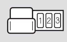
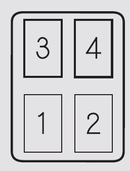
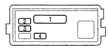
Relay
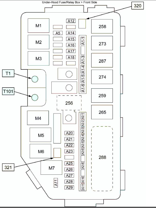
 Acura ILX – fuse box – engine compartment (front side)
| Position |
Description |
| M1 |
Blower Motor Relay |
| M2 |
Starter Cut Relay 1 |
| M3 |
A/C Condenser Fan Relay |
| M4 |
Ignition Coil Relay |
| M5 |
Starter Cut Relay 2 |
| M6 |
PGM-FI Subrelay |
| M7 |
Rear Window Defogger Relay |
| 256 |
ELD |
| 258 |
Fan Control Relay |
| 259 |
Fog Light Relay |
| 265 |
Horn Relay |
| 273 |
Radiator Fan Relay |
| 274 |
NC Compressor Clutch Relay |
| 287 |
Windshield Wiper Motor Relay |
| 288 |
Relay Circuit Board |
| 320 |
Diode D |
| 321 |
Diode C |
Connector
| Position |
Connector name |
Connector type |
| T1 |
T1 |
Component Connector |
| T101 |
T101 |
Component Connector |
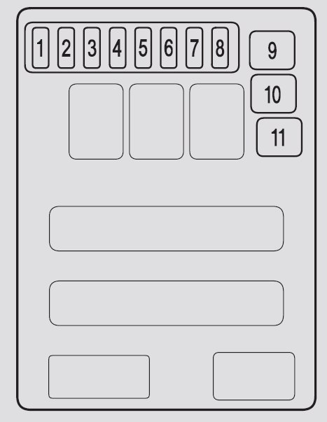
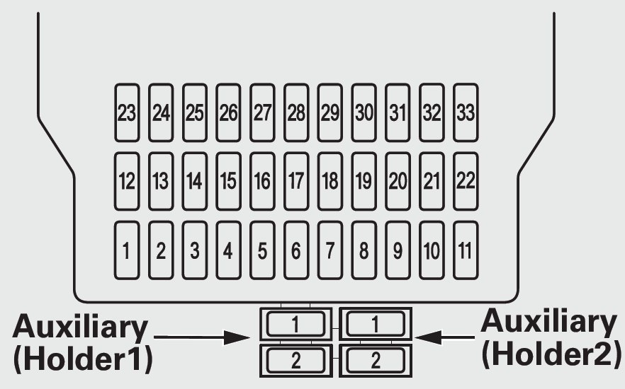
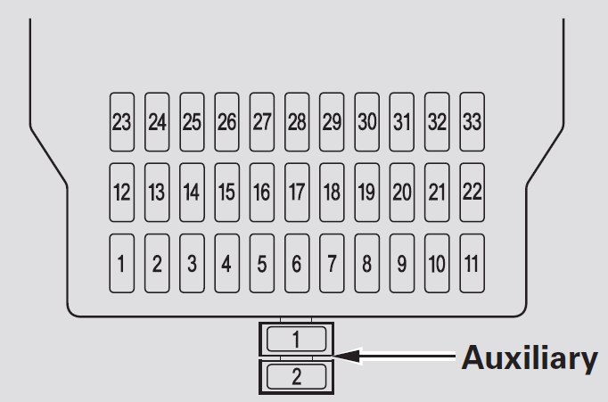
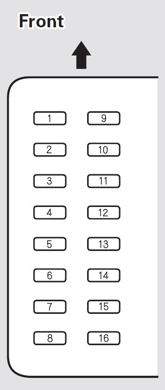
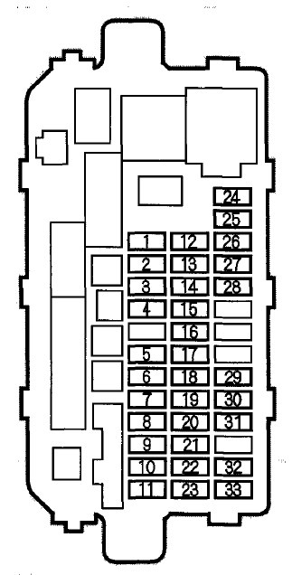
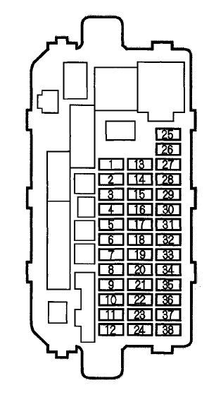
Interior fuse box
| Fuse |
Circuit protected |
Ampere rating [A] |
| 1 |
— |
— |
| 2 |
ACG |
15 |
| 3 |
SRS |
10 |
| 4 |
Fuel pump |
15 |
| 5 |
Meter |
7,5 |
| 6 |
Power Window |
7,5 |
| 7 |
VB SOL* |
7,5 |
| 8 |
Door Lock Motor 2 (Unlock) |
15 |
| 9 |
Door Lock Motor 1 (Unlock) |
15 |
| 10 |
— |
— |
| 11 |
Moonroof |
20 |
| 12 |
Driver’s Power Seat Sliding* |
20 |
| 13 |
Driver’s Power Seat Reclining* |
20 |
| 14 |
Seat Heaters* |
15 |
| 15 |
Driver’s Door Lock Motor (Unlock) |
|
| 16 |
— |
— |
| 17 |
— |
— |
| 18 |
— |
— |
| 19 |
ACC |
7,5 |
| 20 |
ACC Key Lock |
7,5 |
| 21 |
Daytime Running Lights |
7,5 |
| 22 |
HAC |
7,5 |
| 23 |
HYBRID A/C |
7,5 |
| 24 |
ABS/VSA |
7,5 |
| 25 |
ACC |
7,5 |
| 26 |
— |
— |
| 27 |
Accessory Power Socket |
20 |
| 28 |
— |
— |
| 29 |
ODS |
7,5 |
| 30 |
Driver’s Door Lock Motor (Lock) |
10 |
| 31 |
SMART |
10 |
| 32 |
Door Lock Motor 2 (Lock) |
15 |
| 33 |
Door Lock Motor 1 (Lock) |
15 |
| 34 |
Small Lights |
7,5 |
| 35 |
Illumination |
7,5 |
| 36 |
— |
— |
| 37 |
Premium Audio* |
20 |
| 38 |
Left Headlight High Beam |
10 |
| 39 |
Right Headlight High Beam |
10 |
| 40 |
TPMS* |
7,5 |
| 41 |
Door Lock |
20 |
| 42 |
Driver’s Power Window |
20 |
| 43 |
Rear Passenger’s Side Power Window |
20 |
| 44 |
Front Passenger’s Side Power Window |
20 |
| 45 |
Rear Driver’s Side Power Window |
20 |
| 46 |
— |
— |
* Not available on all models
WARNING: Terminal and harness assignments for individual connectors will vary depending on vehicle equipment level, model, and market.