Mazda RX-8 (2007 – 2008) – fuse box diagram
Year of production: 2007, 2008
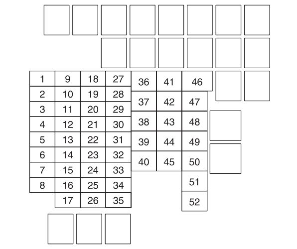
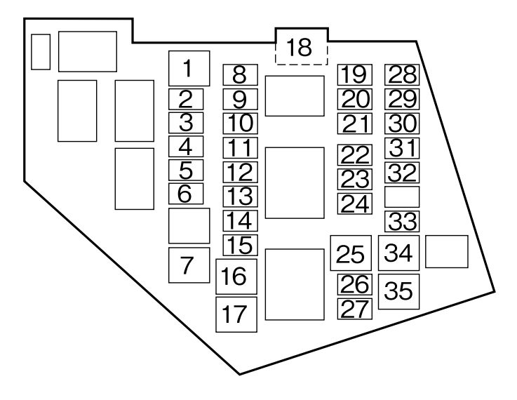
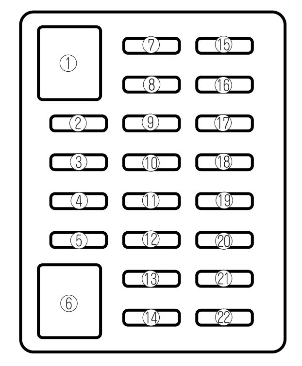
Fuse block (Engine compartment)
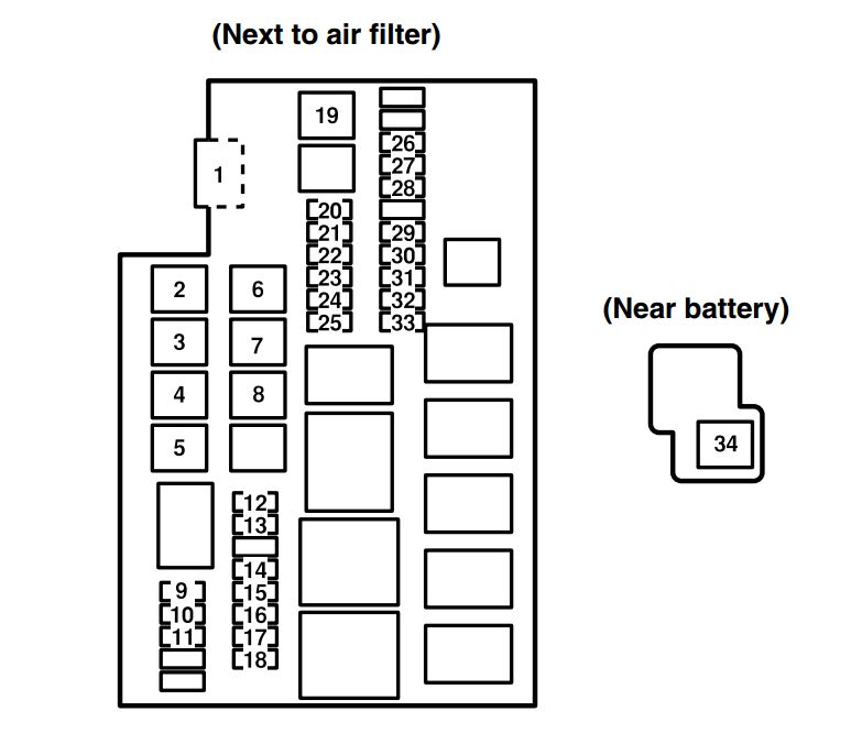
engine compartment
| Position | Description | Fuse rating [A] | Protected component |
| 1 | MAIN | 120 | For protection of all circuits |
| 2 | HEATER | 40 | Heater |
| 3 | AIR PUMP | 60 | Air pump |
| 4 | BTN | 30 | Power windows, Power door locks, Illuminated entry system, Moonroof* |
| 5 | DEFOG | 50 | Rear window defroster |
| 6 | FAN | 40 | Electric fan |
| 7 | ABS/DSC | 60 | ABS, DSC* |
| 8 | ACC | 30 | Lighter, Power control mirror, Accessory socket, Audio system |
| 9 | HEAD | 15 | Headlight high beams*, Headlight cleaner* |
| 10 | HEAD LOW R | 15 | Headlight low beam (RH) |
| 11 | HEAD LOW L | 15 | Headlight low beam (LH) |
| 12 | DRL | 15 | DRL* (Headlight high beams) |
| 13 | DSC | 30 | DSC* |
| 14 | SEAT WARM | 20 | Seat warmer* |
| 15 | H/CLEAN | 20 | Headlight cleaner* |
| 16 | R.FOG | 10 | — |
| 17 | FOG | 15 | Fog lights* |
| 18 | A/C MAG | 10 | Air conditioner |
| 19 | IG | 30 | For protection of various circuits |
| 20 | IG KEY | 15 | For protection of various circuits |
| 21 | STOP | 15 | Brake lights |
| 22 | FUEL PUMP | 20 | Fuel pump |
| 23 | HORN | 15 | Horn |
| 24 | HAZARD | 15 | Hazard warning flashers, Turn signals |
| 25 | ETV | 15 | Electric throttle valve |
| 26 | WIPER | 20 | Windshield wiper and washer |
| 27 | P.WIND | 20 | — |
| 28 | ENGINE | 15 | Engine control system, Supplemental restraint system, ABS, Power steering |
| 29 | TAIL | 10 | Taillights, License plate light, Parking lights, Front side-maker lights, Rear side-marker lights |
| 30 | ILLUMI | 10 | Illuminated entry system |
| 31 | EGI COMP1 | 10 | Engine control system |
| 32 | EGI COMP2 | 10 | Engine control system |
| 33 | EGI INJ | 15 | Fuel injector |
| 34 | EPS | 60 | Power steering |
| * Some models | |||
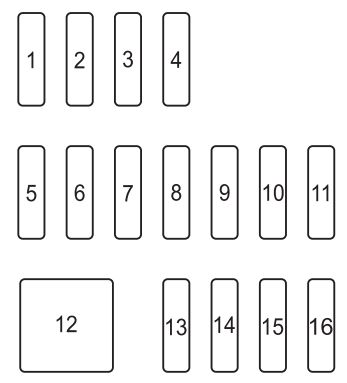
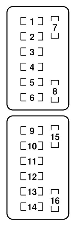
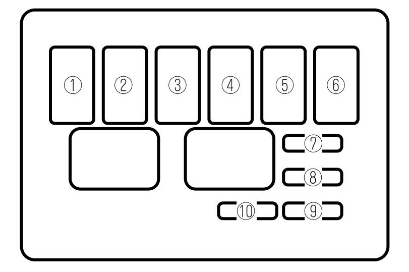
Fuse panel (Driver’s side)
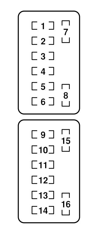
driver’s side
| Position | Description | Fuse rating [A] | Protected component |
| 1 | CIGAR | 15 | Lighter |
| 2 | ACC | 7,5 | Audio system, Power control mirror |
| 3 | AUX PWR | 20 | Accessory socket |
| 4 | A/C | 7,5 | Air conditioner |
| 5 | METER | 10 | Instrument cluster |
| 6 | TCM | 10 | Transmission control system |
| 7 | SPARE | 7,5 | — |
| 8 | SPARE | 20 | — |
| 9 | M.DEF | 10 | Mirror defroster* |
| 10 | DSC | 7,5 | DSC* |
| 11 | AUDIO | 20 | Audio system* |
| 12 | D.LOCK | 30 | Power door locks, Moonroof* |
| 13 | P.WIND | 30 | Power windows |
| 14 | ROOM | 15 | Interior lights |
| 15 | SPARE | 15 | — |
| 16 | SPARE | 10 | — |
| * Some models | |||
WARNING: Terminal and harness assignments for individual connectors will vary depending on vehicle equipment level, model, and market.