Pontiac Torrent (2008 – 2009) – fuse box diagram
Year production: 2008, 2009
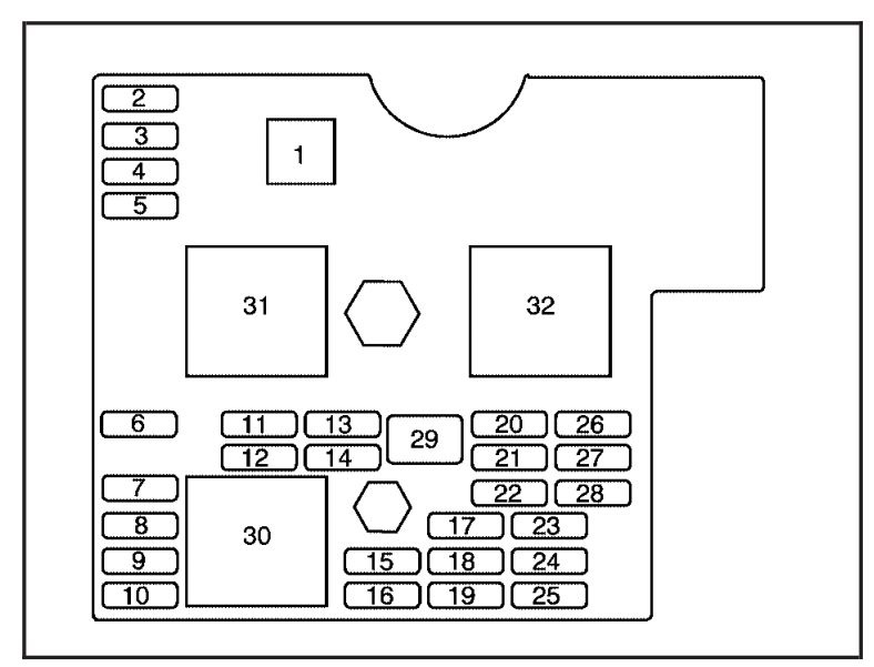
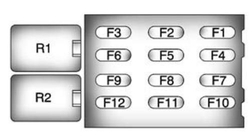
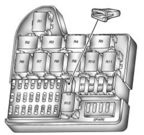
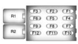
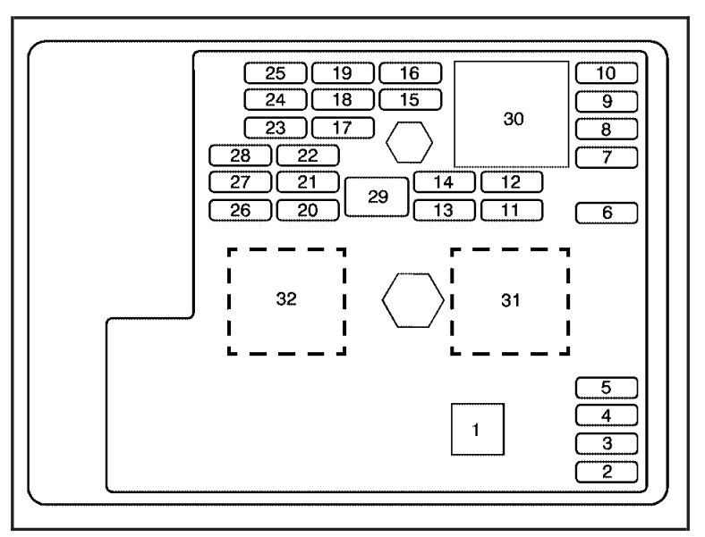
Instrument Panel Fuse Block
The instrument panel fuse block is located on the passenger side of the center console, to the left of the glove box near the floor.
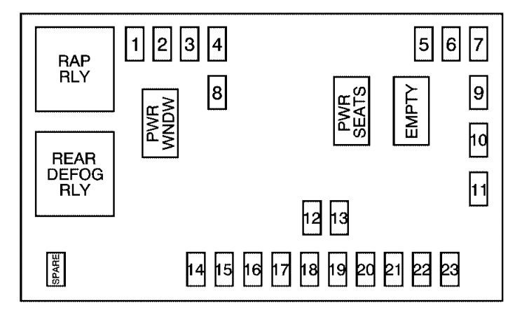
| Fuses | Usage |
| 1 | Sunroof |
| 2 | Rear Seat Entertainment |
| 3 | Rear Wiper |
| 4 | Liftgate |
| 5 | Airbags |
| 6 | Heated Seats |
| 7 | Driver Side Turn Signal |
| 8 | Door Locks |
| 9 | Automatic Occupant Sensing Module |
| 10 | Power Mirrors |
| 11 | Passenger Side Turn Signal |
| 12 | Amplifier |
| 13 | Steering Wheel Illumination |
| 14 | Infotainment |
| 15 | Climate Control System, Remote Function Actuator |
| 16 | Canister Vent |
| 17 | Radio |
| 18 | Cluster |
| 19 | Ignition Switch |
| 20 | Body Control Module |
| 21 | OnStar® |
| 22 | Center High-Mounted Stoplamp, Dimmer |
| 23 | Interior Lights |
| Relays | Usage |
| RAP RLY | Retained Accessory Power Relay |
| REAR DEFOG RLY | Rear Defogger Relay |
| Circuit Breaker | Usage |
| PWR WNDW | Power Windows |
| PWR SEATS | Power Seats |
| EMPTY | Empty |
| Misc. | Usage |
| PLR | Fuse Puller |
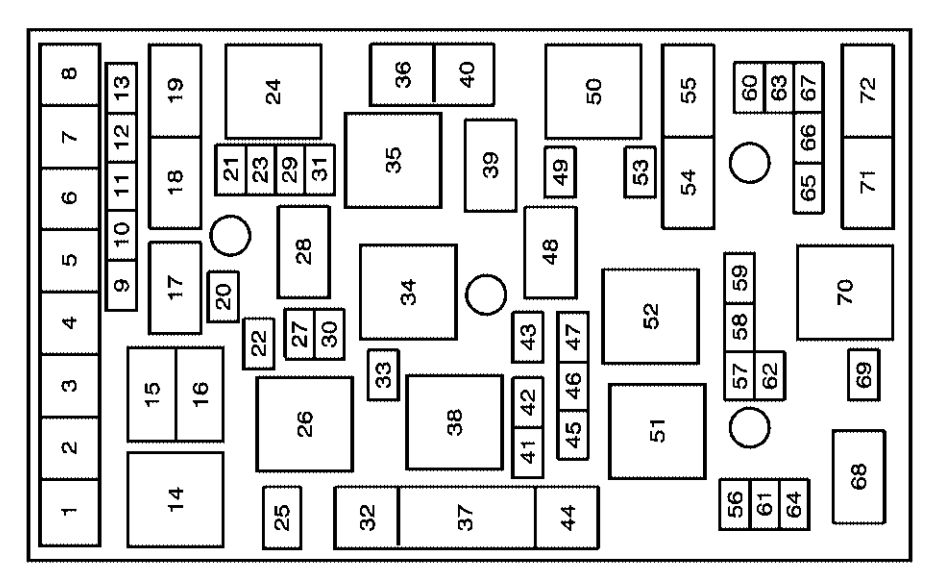
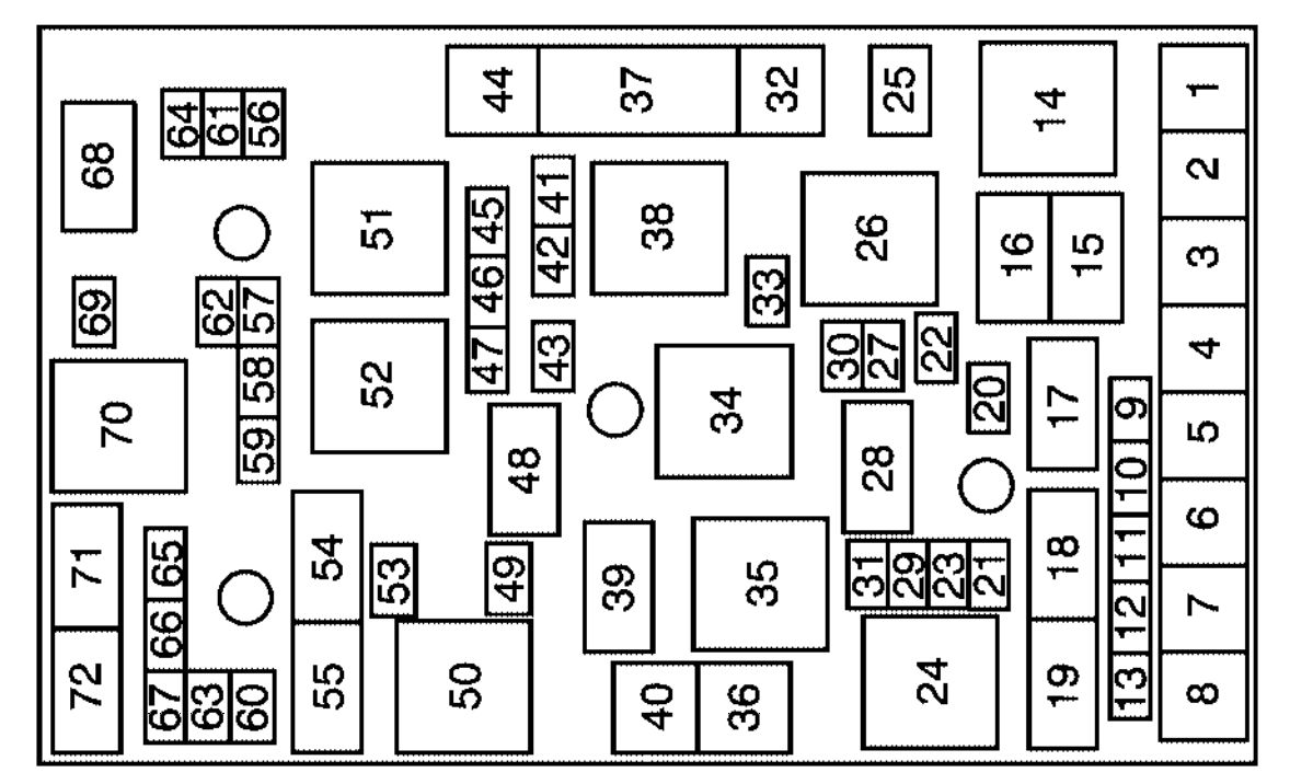
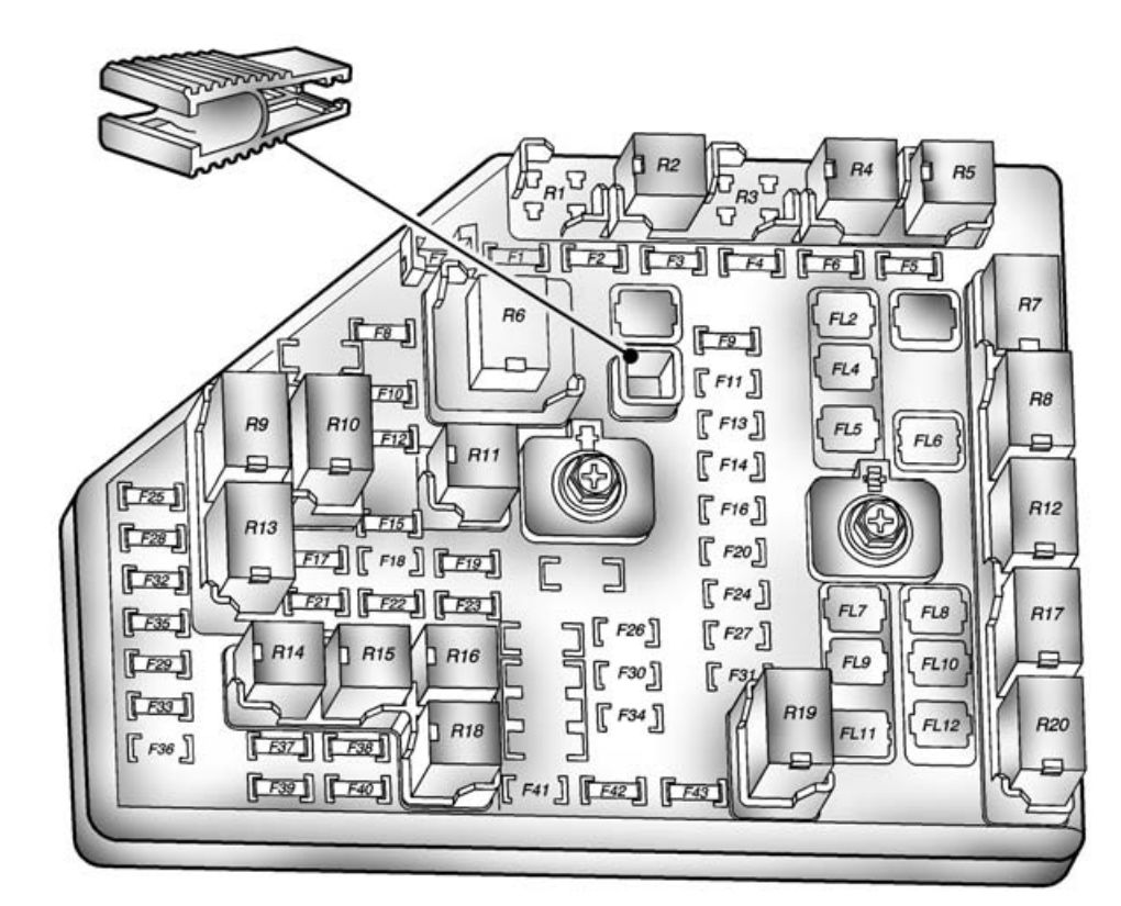
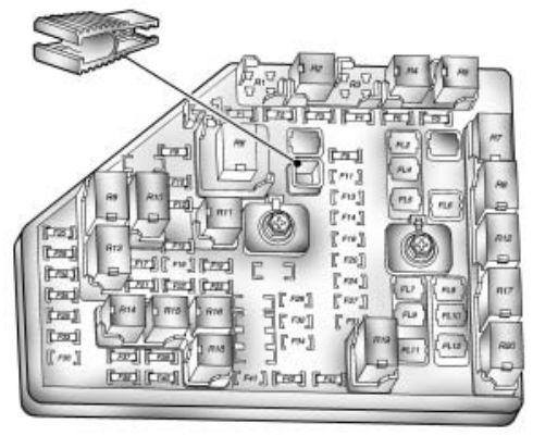
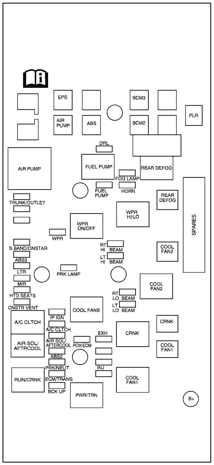
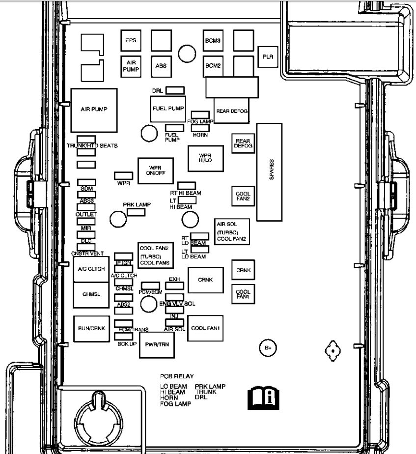
Engine Compartment Fuse Block
The engine compartment fuse block is located on the driver side of the engine compartment.
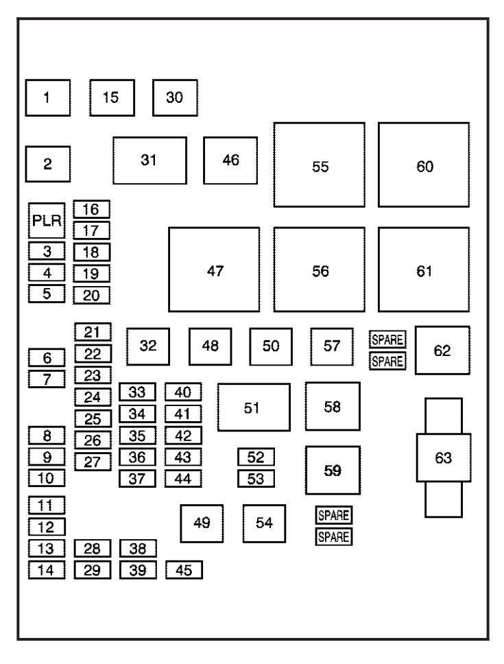
| Fuses | Usage |
| 1 | Cooling Fan 2 |
| 2 | Cooling Fan 1 |
| 3 | Auxiliary Power |
| 4 | Rear HVAC |
| 5 | Spare |
| 6 | Spare |
| 7 | Antilock Brake System |
| 8 | Air Conditioning Clutch |
| 9 | Driver Side Low-Beam |
| 10 | Daytime Running Lamp 2 |
| 11 | Passenger Side High-Beam |
| 12 | Passenger Side Park Lamp |
| 13 | Horn |
| 14 | Driver Side Park Lamp |
| 15 | Starter |
| 16 | Electronic Throttle Control, Engine Control Module |
| 17 | Emission Device 1 |
| 18 | Even Coils, Injectors |
| 19 | Odd Coils, Injectors |
| 20 | Emission Device 2 |
| 21 | Spare |
| 22 | Powertrain Control Module, Ignition |
| 23 | Transmission |
| 24 | Mass Airflow Sensor |
| 25 | Airbag Display |
| 26 | Spare |
| 27 | Stoplamp |
| 28 | Passenger Side Low-Beam |
| 29 | Driver Side High-Beam |
| 30 | Battery Main 3 |
| 32 | Spare |
| 33 | Engine Control Module, Battery |
| 34 | Transmission Control Module, Battery |
| 35 | Trailer Park Lamp |
| 36 | Front Wiper |
| 37 | Driver Side Trailer Stoplamp, Turn Signal |
| 38 | Spare |
| 39 | Fuel Pump |
| 40 | Not Used |
| 41 | All-Wheel Drive |
| 42 | Regulated Voltage Control |
| 43 | Passenger Side Trailer Stoplamp, Turn Signal |
| 44 | Spare |
| 45 | Front, Rear Washer |
| 48 | Rear Defogger |
| 49 | Antilock Brake System Motor |
| 50 | Battery Main 2 |
| 52 | Daytime Running Lamps |
| 53 | Fog Lamps |
| 54 | Climate Control System Blower |
| 57 | Battery Main 1 |
| 63 | Electric Power Steering |
| Relays | Usage |
| 31 | Ignition Main |
| 46 | Air Conditioning Compressor Clutch |
| 47 | Powertrain |
| 51 | Spare |
| 55 | Crank |
| 56 | Fan 1 |
| 58 | Passenger Side Trailer Stoplamp, Turn Signal |
| 59 | Driver Side Trailer Stoplamp, Turn Signal |
| 60 | Fan 3 |
| 61 | Fan 2 |
| 62 | Fuel Pump |
WARNING: Terminal and harness assignments for individual connectors will vary depending on vehicle equipment level, model, and market.