HUMMER H2 (2006) – fuse box diagram
Year of production: 2006
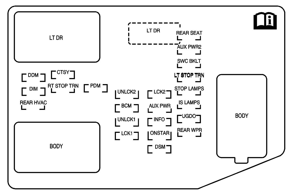
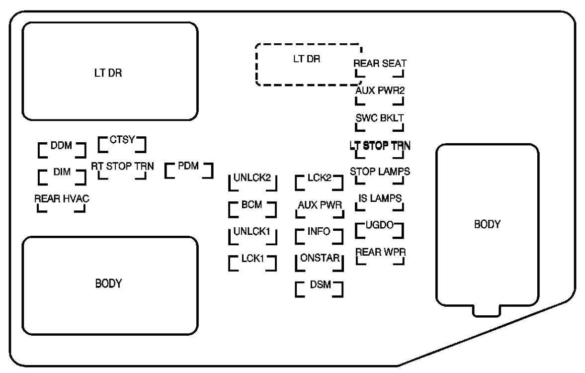
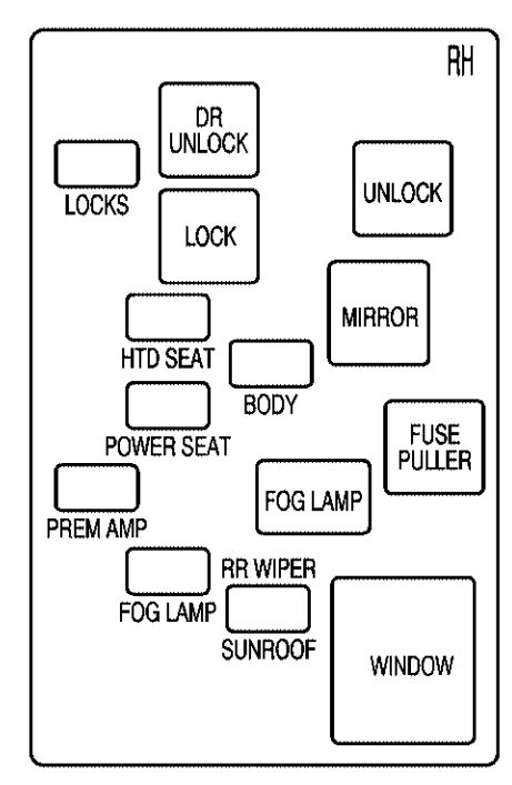
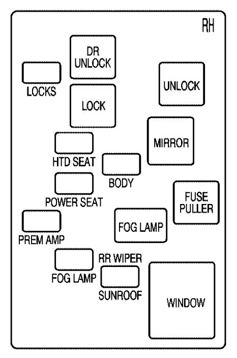
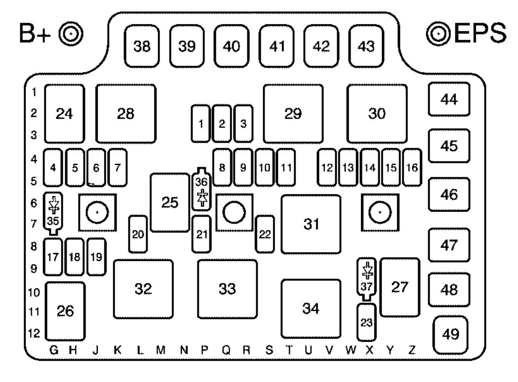
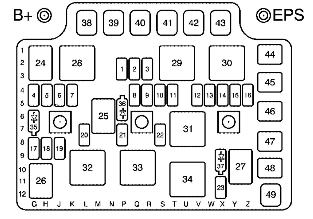
Instrument Panel Fuse Block
The fuse block access door is located on the driver’s side edge of the instrument panel.
| Fuses | Usage |
| RR Wiper | Rear Window Wiper Switch |
| SEO ACCY | Special Equipment Option Accessory |
| WS WPR | Windshield Wipers |
| TBC ACCY | Truck Body Controller Accessory |
| IGN 3 | Rear Heated Seats Module |
| 4WD | Four-Wheel Drive Switch, Air Suspension Switch/Module |
| HTR A/C | Not Used |
| LOCK | Power Door Lock Relay (Lock Function) |
| HVAC 1 | Inside Rearview Mirror, Climate Control System |
| L DOOR | Driver’s Door Harness Connection |
| CRUISE | Cruise Control |
| UNLOCK | Power Door Lock Relay (Unlock Function) |
| RR FOG LP | Not Used |
| BRAKE | Brake Switch |
| DRIVER UNLOCK | Power Door Lock Relay (Driver’s Door Unlock Function) |
| IGN 0 | Brake Transmission Shift Interlock, Powertrain Control Module, Transmission |
| TBC IGN 0 | Truck Body Controller |
| VEH CHMSL | Vehicle and Trailer High Mounted Stoplamp |
| LT TRLR ST/TRN | Left Turn Signal/Stop Trailer |
| LT TRN | Left Turn Signals and Sidemarkers |
| VEH STOP | Vehicle Stoplamps, Brake Module, Electronic Throttle Control Module |
| RT TRLR ST/TRN | Right Turn Signal/Stop Trailer |
| RT TRN | Right Turn Signals and Sidemarkers |
| BODY | Harness Connector |
| DDM | Driver Door Module |
| LOCKS | Rear Doors and Liftgate Power Lock Relay Feed |
| ECC | Liftgate |
| TBC 2C | Truck Body Controller |
| FLASH | Flasher Module |
| CB LT DOORS | Left Rear Power Window Circuit Breaker and Driver Door Module |
| TBC 2B | Truck Body Controller |
| TBC 2A | Truck Body Controller |
| Circuit Breaker | Usage |
| AUX PWR 2 | DrivMidgate Controller (SUT Only)er Door Harness Connection |
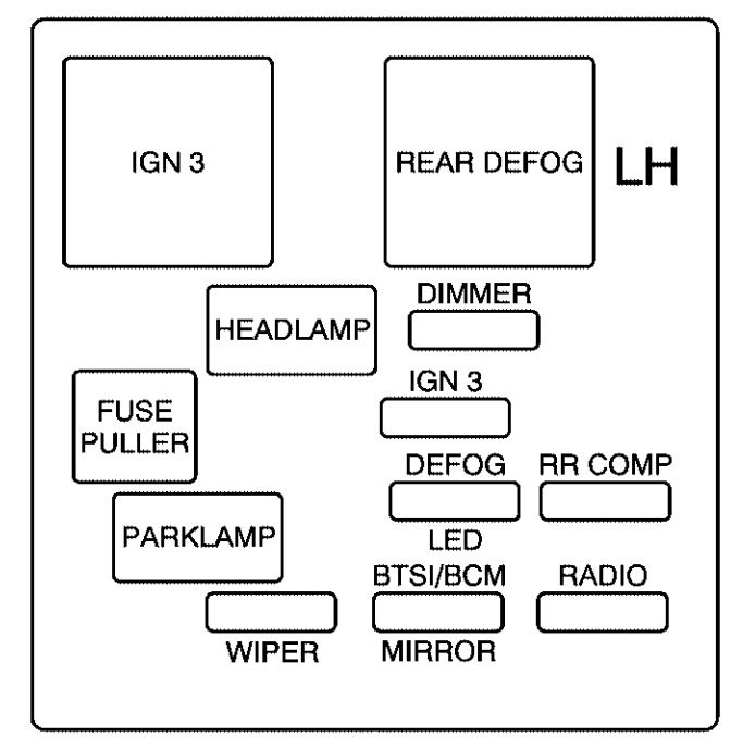
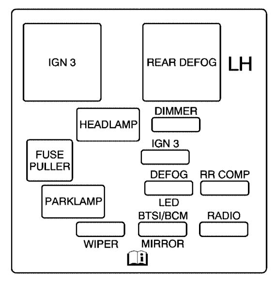
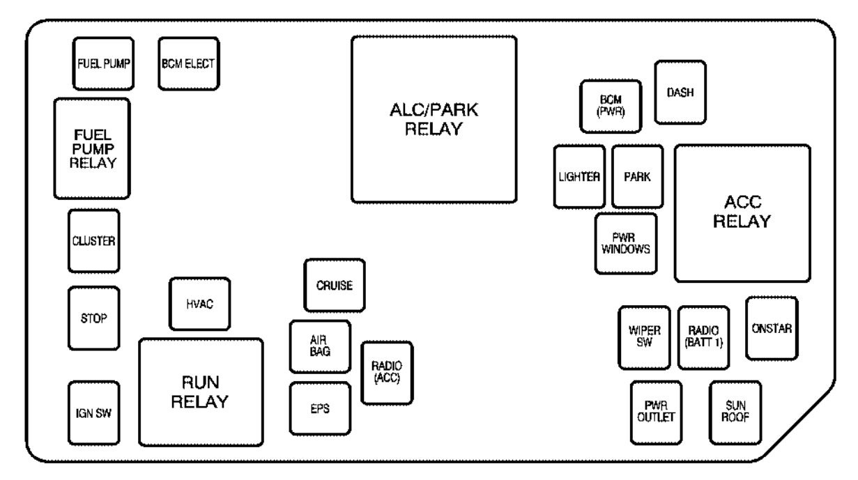
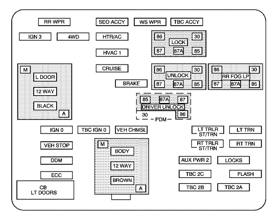
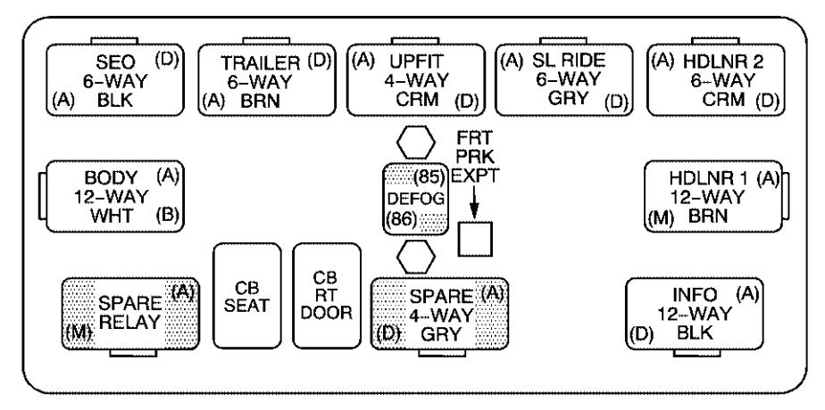
Center Instrument Panel Fuse Block
The center instrument panel utility block is located underneath the instrument panel, to the left of the steering column.
| Device | Usage |
| SEO | Special Equipment Option |
| TRAILER | Trailer Brake Wiring, Off-Road Lamps Harness Connector |
| UPFIT | Upfitter (Not Used) |
| SL RIDE | Ride Control (Not Used) |
| HDLR 2 | Headliner Wiring Connector 2 |
| BODY | Body Wiring Connector |
| DEFOG | Rear Defogger Relay |
| HDLNR 1 | Headliner Wiring Connector 1 |
| SPARE RELAY | Not Used |
| CB SEAT | Driver and Passenger Seat Module Circuit Breaker |
| CB RT DOOR | Rear Right Power Window, Passenger Door Module |
| SPARE | Not Used |
| INFO | Not Used |
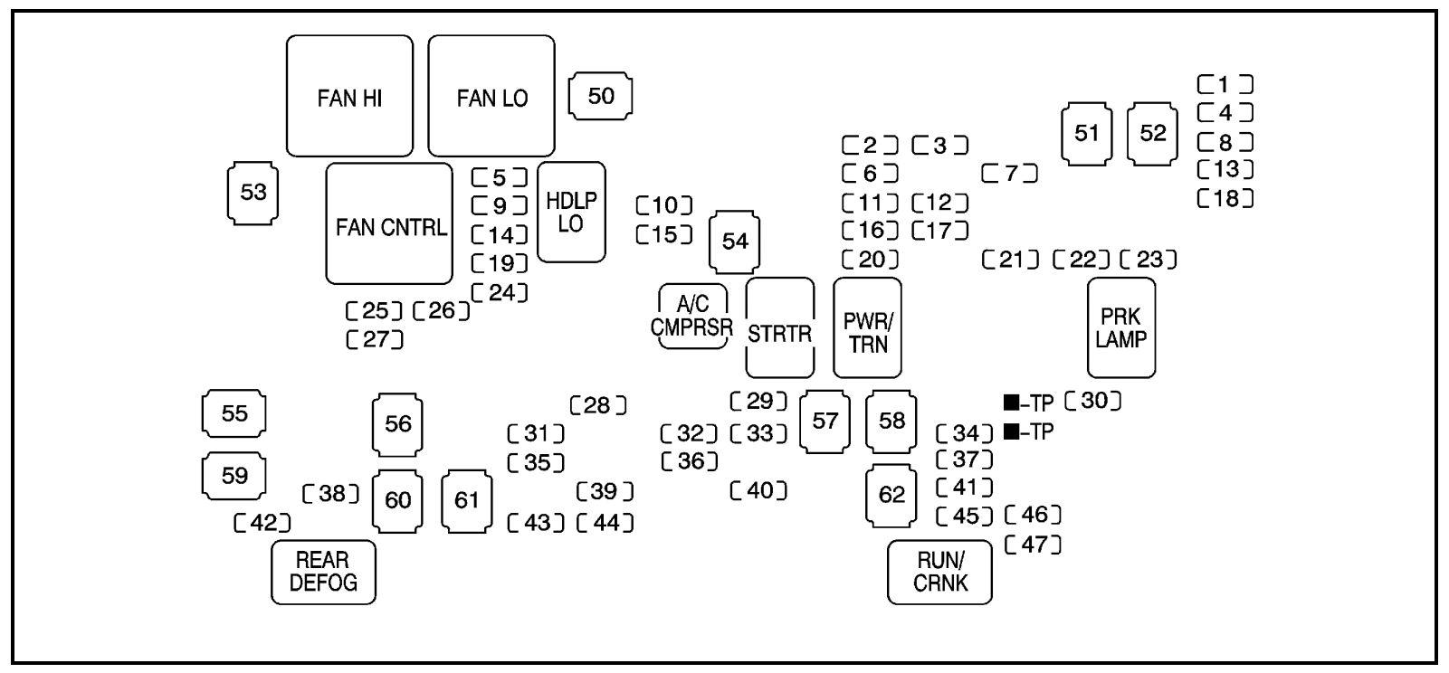
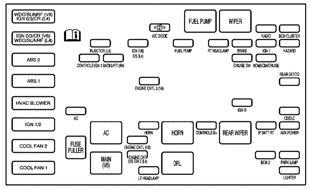
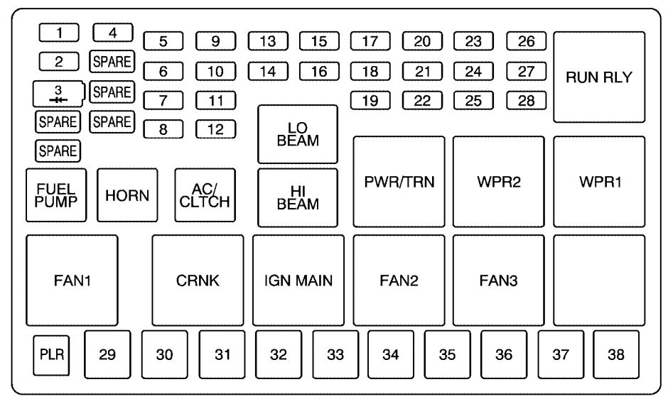
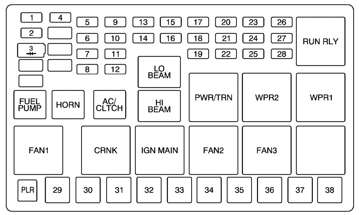
Underhood Fuse Block
The underhood fuse block in the engine compartment is located on the driver’s side of the vehicle near the battery.
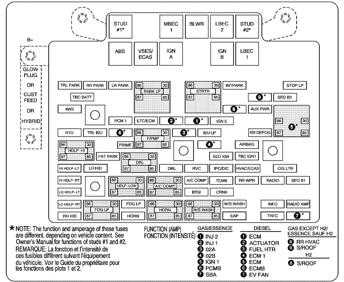
*1 — Gasoline Engine and Fuel Injection Rail #2.
*2 — Gasoline Engine and Fuel Injection Rail #1.
*3 — Gasoline Engine; Oxygen Sensors.
*4 — Gasoline Engine; Oxygen Sensors.
*5 — Ignition 1
*6 — Powertrain Control Module, Fuel Pump.
*7 — Sunroof.
*8 — Not Used.
| Fuses | Usage |
| GLOW PLUG | Not Used |
| CUST FEED | Gasoline Accessory Power |
| HYBRID | Not Used |
| WSW/HTR | Heated Windshield Washer (Special Edition Only) |
| STUD #1 | Accessory Power/Trailer Wiring |
| MBEC 1 | Mid Bussed Electrical Center Power Feed, Front Seats, Right Doors |
| BLWR | Front Climate Control Fan |
| LBEC 2 | Left Bussed Electrical Center, Door Modules, Door Locks, Auxiliary Power Outlet—Rear Cargo Area and Instrument Panel |
| STUD #2* | Accessory Power/Trailer Wiring Brake Feed |
| ABS | Anti-lock Brakes |
| VSES/ECAS | Electronically Controlled Air Suspension |
| IGN A | Ignition Switch |
| IGN B | Ignition Switch |
| LBEC 1 | Left Bussed Electrical Center, Left Doors, Truck Body Controller, Flasher Module |
| TRL PARK | Parking Lamps Trailer Wiring |
| RR PARK | Passenger’s Side Rear Parking and Sidemarker Lamps |
| LR PARK | Driver’s Side Rear Parking and Sidemarker Lamps |
| PARK LP | Parking Lamps Relay |
| STRTR | Starter Relay |
| INTPARK | Roof Marker Lamps |
| STOP LP | Stoplamps |
| TBC BATT | Truck Body Controller Battery Feed |
| SEO B2 | Off-Road Lamps |
| 4WS | Not Used |
| AUX PWR | Instrument Panel Outlets, Rear Cargo Area Power Outlets, Console |
| PCM 1 | Powertrain Control Module |
| ETC/ECM | Electronic Throttle Control, Electronic Brake Controller |
| IGN E | Instrument Panel Cluster, Air Conditioning Relay, Turn Signal/Hazard Switch, Starter Relay, Electronic Brake Controller TC2 Mode Switch |
| RTD | Electronic Brake Controller Battery Feed |
| TRL B/U | Backup Lamps Trailer Wiring |
| F/PMP | Fuel Pump (Relay) |
| B/U LP | Back-up Lamps, Automatic Transmission Shift Lock Control System |
| RR DEFOG | Rear Window Defogger |
| HDLP-HI | Headlamp High Beam Relay |
| PRIME | Not Used |
| AIRBAG | Supplemental Inflatable Restraint System |
| FRT PARK | Front Parking Lamps, Sidemarker Lamps |
| DRL | Daytime Running Lamps (Relay |
| SEO IGN | Rear Defog Relay |
| TBC IGN1 | Truck Body Controller Ignition |
| HI HDLP-LT | Driver’s Side High Beam Headlamp |
| LH HID | Not Used |
| DRL | Daytime Running Lamps |
| RVC | Regulated Voltage Control |
| IPC/DIC | Instrument Panel Cluster/ Driver Information Center |
| HVAC/ECAS | Climate Control Controller/Electronically Controlled Air Suspension |
| CIG LTR | Cigarette Lighter |
| HI HDLP-RT | Passenger’s Side High Beam Headlamp |
| HDLP-LOW | Headlamp Low Beam Relay |
| A/C COMP | Air Conditioning Compressor Relay |
| A/C COMP | Air Conditioning Compresso |
| TCMB | Transmission Control Module |
| RR WPR | Rear Wiper/Washer |
| RADIO | Audio System |
| SEO B1 | Mid Bussed Electrical Center, Universal Home Remote System, Rear Heated Seats |
| LO HDLP-LT | Driver’s Side Headlamp Low Beam |
| BTSI | Brake Transmission Shift Interlock System |
| CRNK | Starting System |
| LO HDLP-RT | Passenger’s Side Headlamp Low Beam |
| FOG LP | Not Used |
| FOG LP | Not Used |
| HORN | Horn Relay |
| W/S WASH | Windshield and Rear Window Washer Pump Relay |
| W/S WASH | Windshield and Rear Window Washer Pump Relay |
| INFO | OnStar® |
| RADIO AMP | Radio Amplifier |
| RH HID | Not Used |
| HORN | Horn |
| EAP | Not Used |
| TREC | Four-Wheel Drive Module |
| SBA | Not Used |
WARNING: Terminal and harness assignments for individual connectors will vary depending on vehicle equipment level, model, and market.