Buick Rendezvous (2003) – fuse box diagram
Year of production: 2003
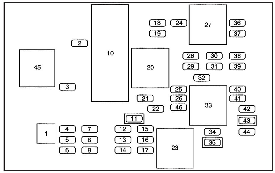
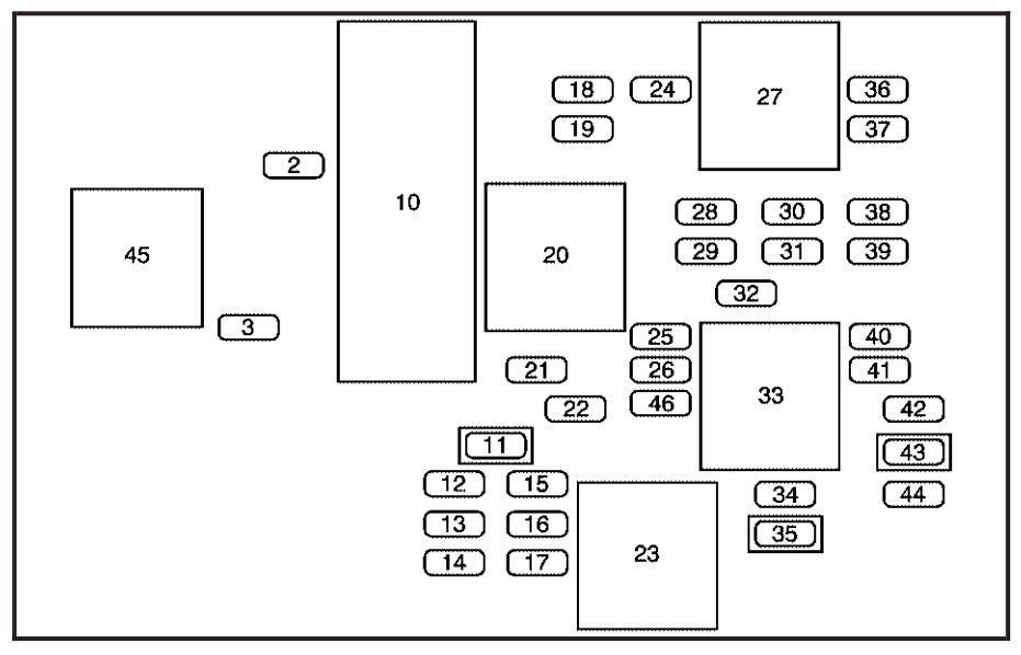
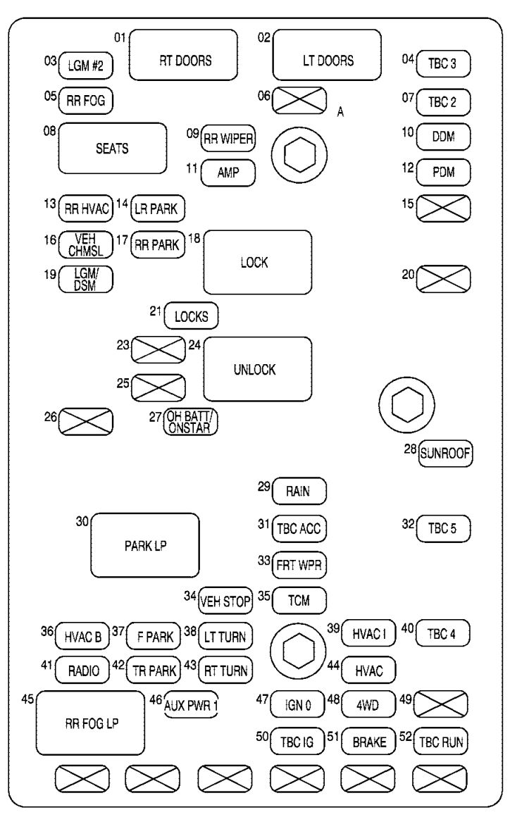
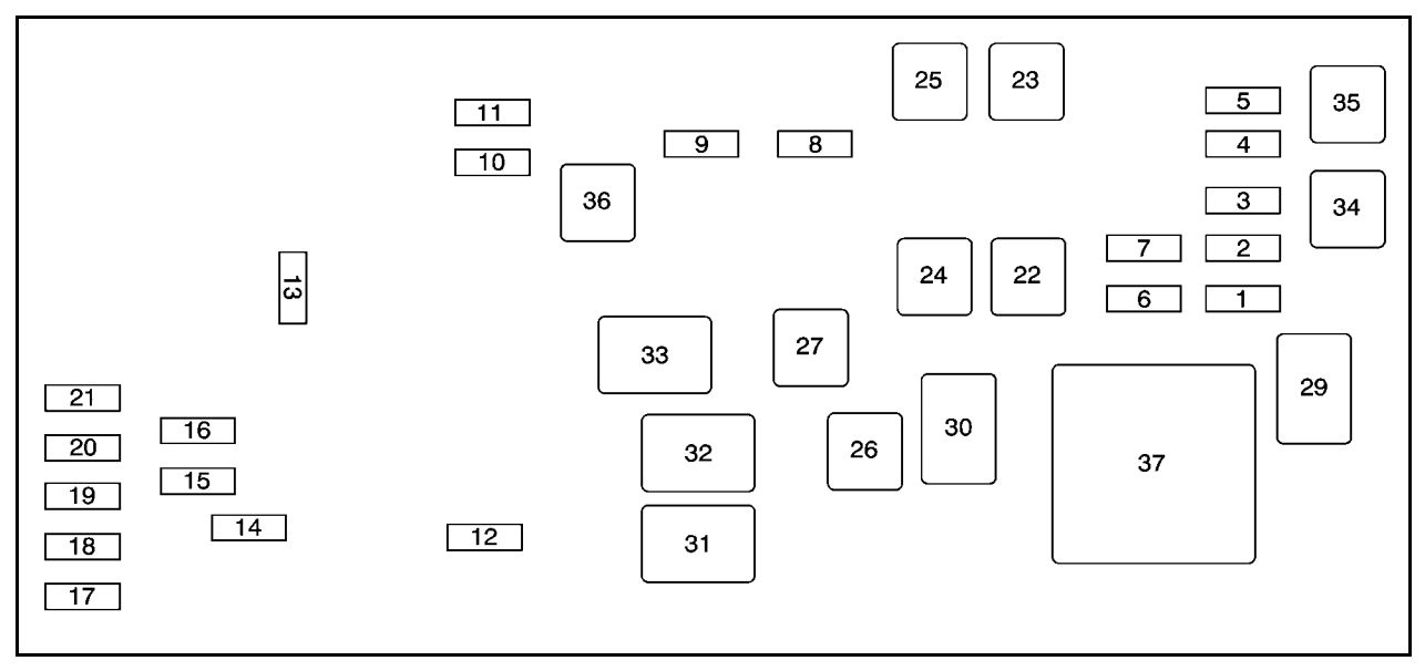
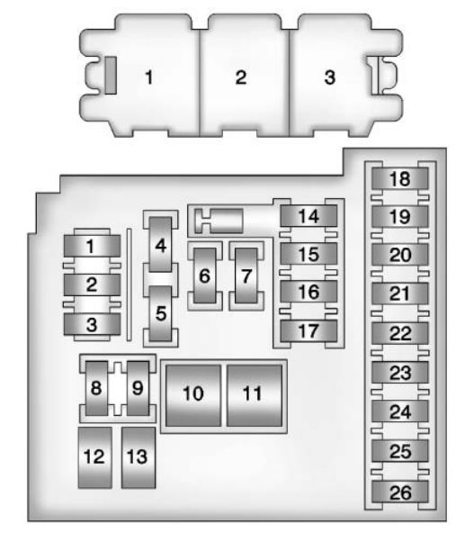
Floor Console Fuse Block
The floor console fuse block is located to the left of the glove box near the floor.
| Fuses | Usage |
| 1 | Fuse Puller |
| 2 | Steering Wheel Radio Controls |
| 3 | Power Door Locks |
| 4 | Spare |
| 5 | Spare |
| 6 | Spare |
| 7 | Spare |
| 8 | Spare |
| 9 | Spare |
| 10 | Turn Signal and Hazard Lamp Flashers |
| 11 | Power Seats |
| 12 | Electronic Level Control (ELC) Compressor |
| 13 | Liftgate and Endgate |
| 14 | Rear Auxiliary Power Outlet |
| 15 | Electronic Level Control (ELC) Compressor Relay and Height Sensor |
| 16 | Heated Mirrors |
| 17 | Power Mirrors |
| 18 | Ignition 1 Module |
| 19 | Turn Signal Switch and NSBU Switch |
| 21 | Rear Defogger |
| 22 | Air bag Module |
| 24 | Canister Vent Soloid and TCC Switch |
| 25 | HVAC Blower Motor |
| 26 | HVAC Mode and Temperature Motors and Head-Up Display |
| 28 | Not Used |
| 29 | Windshield Wipers and Washer |
| 30 | Instrument Panel Cluster, BCM, PASS-Key® III |
| 31 | Park Lock Ignition Key Solenoid |
| 32 | Rear Window Wiper/Washer |
| 34 | Power Sunroof |
| 35 | Power Windows |
| 36 | Map Lamps, Courtesy Lamps and Instrument Panel Lights |
| 37 | Radio |
| 38 | UQ3 Radio Amplifier |
| 39 | Head-Up Display |
| 40 | Hazard Flashers |
| 41 | Instrument Panel Cluster, HVAC Control, Security LED and Remote Keyless Entry Mode |
| 42 | PASS-Key® III |
| 44 | Body Control Module (BCM) |
| Relay | Usage |
| 20 | Rear Defogger Relay |
| 23 | IGN3 Relay |
| 27 | Accessory Relay |
| 33 | Retained Accessory Power Relay |
| 43 | Accessory Diode |
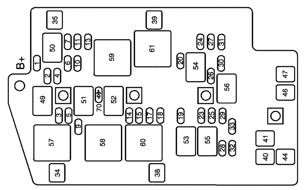
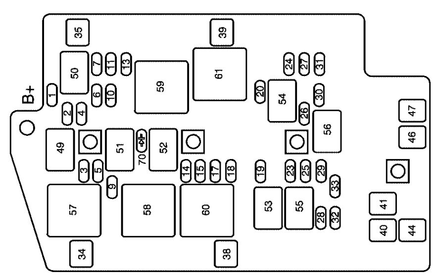
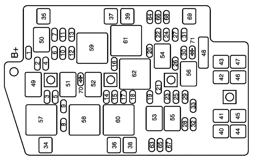
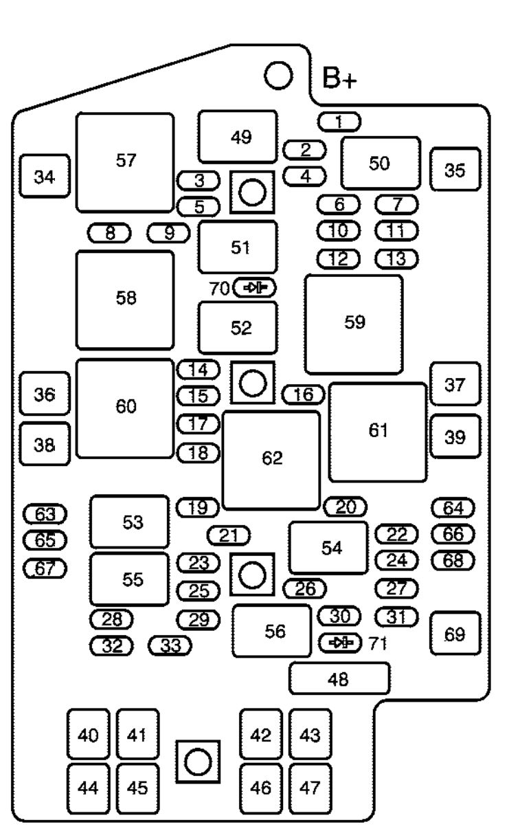
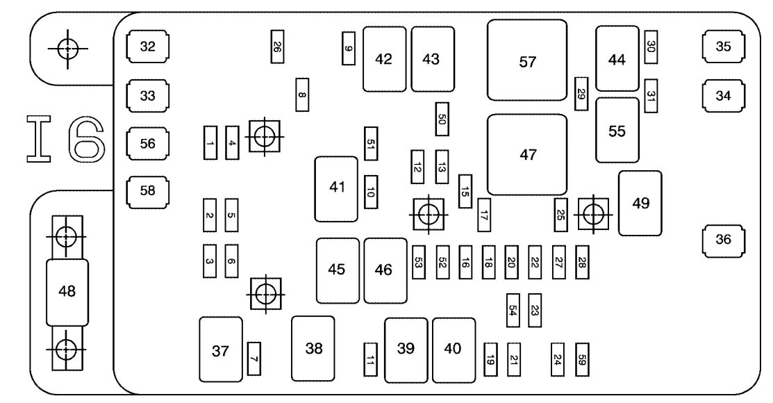
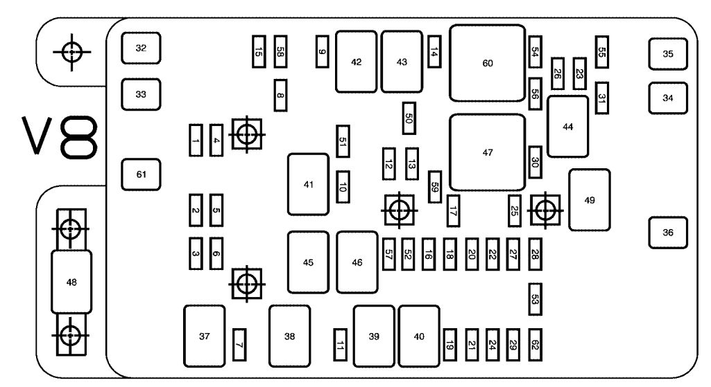
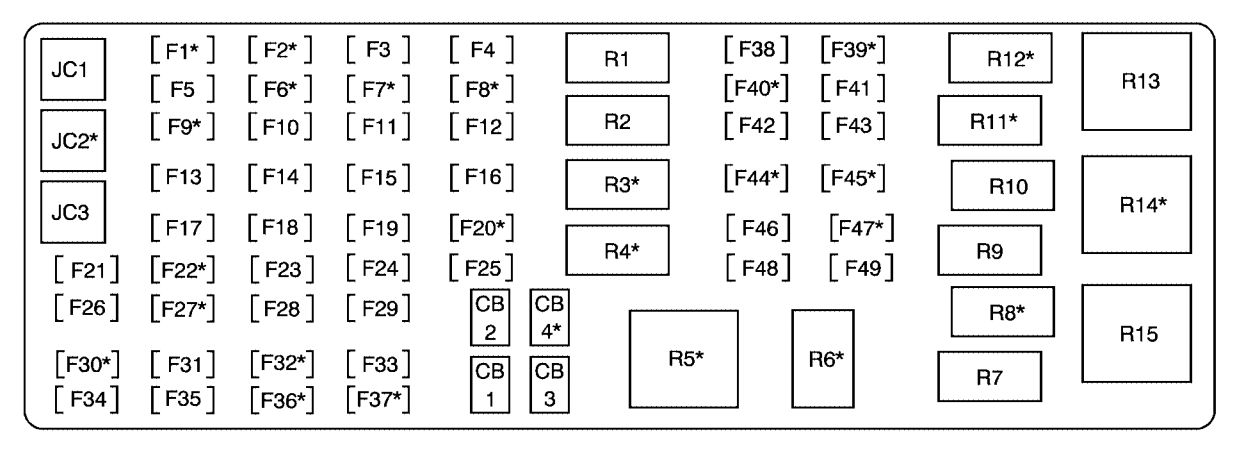
Underhood Fuse Block
This fuse block is located in the engine compartment, on the passenger’s side of the vehicle.
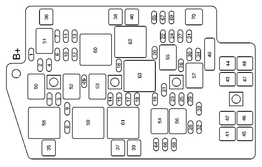
| Fuses | Usage |
| 1 | Fuel Pump |
| 2 | Air Conditioning Compressor Clutch |
| 3 | Horn |
| 4 | Engine Controls-Emissions and Sensors |
| 5 | Power Control Module (PCM)-Battery Power |
| 6 | Anti-Lock Brakes (ABS) Control Module |
| 7 | Transaxle Solenoids |
| 8 | Spare |
| 9 | ABS Solenoids Valves |
| 10 | Oxygen Sensors-Emissions Control |
| 11 | Injectors |
| 13 | Engine Controls |
| 14 | Daytime Running Lamps (DRL) |
| 15 | Passenger’s Low-Beam Headlamp |
| 16 | Spare |
| 17 | Driver’s Low-Beam Headlamp |
| 18 | Driver’s High-Beam Headlamp |
| 19 | Ignition Switch Battery Power |
| 20 | Parking Lamps-Front and Rear |
| 21 | Air Pump-Emissions Controls |
| 22 | Spare |
| 23 | Passenger’s High-Beam Headlamp |
| 24 | Vent Solenoids |
| 25 | Spare |
| 26 | Front Fog Lamps |
| 27 | Ignition Relay, Neutral Start Switch, Powertrain Control Module (PCM) |
| 28 | Body Control Module-Battery Power |
| 29 | L Band, Remote Digital Radio Receiver |
| 30 | All-Wheel Drive (AWD) Module |
| 31 | Cruise Control |
| 32 | Front Power Outlets/Lights, OnStar® |
| 33 | Automatic Transaxle Shift Lock Control System |
| 34 | Spare |
| 35 | Starter Solenoid Battery Fuse |
| 36 | ABS Motor |
| 37 | Spare |
| 38 | Spare |
| 39 | Engine Cooling Fan |
| 40 | Engine Cooling Fan |
| 41 | Main Battery Fuse for Retained Accessory Power Relay and Accessory Relay |
| 42 | Main Battery Fuse for Heated Seats, Air |
| 43 | Spare |
| 44 | Spare |
| 45 | Main Battery Fuse for Power Outlets, Level Control, Power Seats and Mirrors and Body Computer |
| 46 | Spare |
| 47 | Main Battery Fuse for Climate Control Blower and Ignition 3 Relay |
| 48 | Main Battery Fuse for Ignition Switch, Radio, Heads-Up Display, Remote Keyless Entry (RKE), Instrument Cluster, Air Conditioning and Body Computer |
| 64 | Spare |
| 65 | Spare |
| 66 | Spare |
| 67 | Spare |
| 68 | Spare |
| 69 | Spare |
| 70 | Fuse Puller |
 |
Diode for Air Conditioning Compressor Clutch |
| Circuit Breaker | Usage |
| 49 | Spare |
| Relay | Usage |
| 50 | Horn |
| 51 | Fuel Pump |
| 52 | Air Conditioning Clutch |
| 53 | Daytime Running Lamps (DRL) |
| 54 | Low-Beam Headlamps |
| 55 | Parking Lamps |
| 56 | High-Beam Headlamps |
| 57 | Fog Lamps |
| 58 | Starter Relay |
| 59 | Cooling Fan |
| 60 | Ignition 1 Relay |
| 61 | Cooling Fan |
| 62 | Cooling Fan |
| 63 | Air pump |
WARNING: Terminal and harness assignments for individual connectors will vary depending on vehicle equipment level, model, and market.