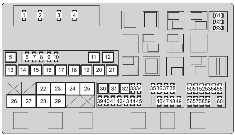
| Fuse |
Ampere rating [A] |
Circuit |
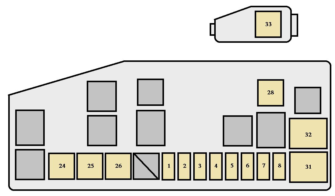
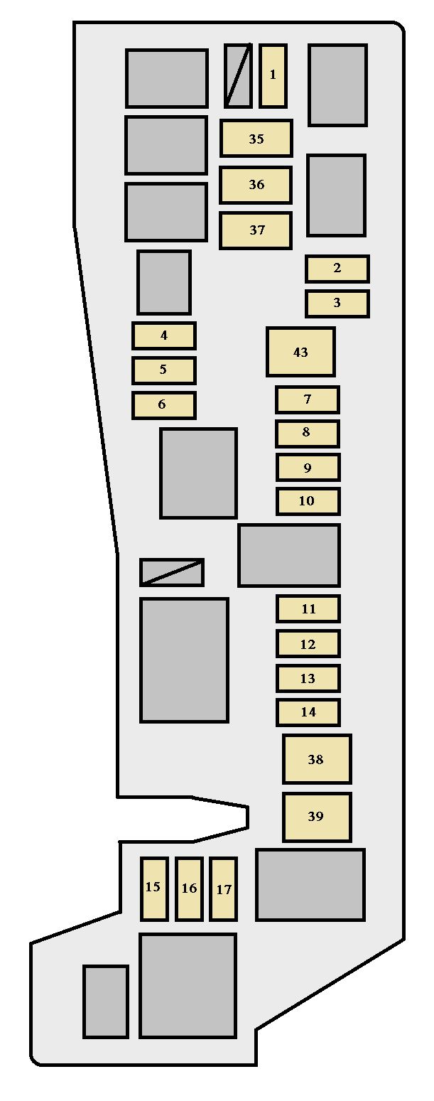
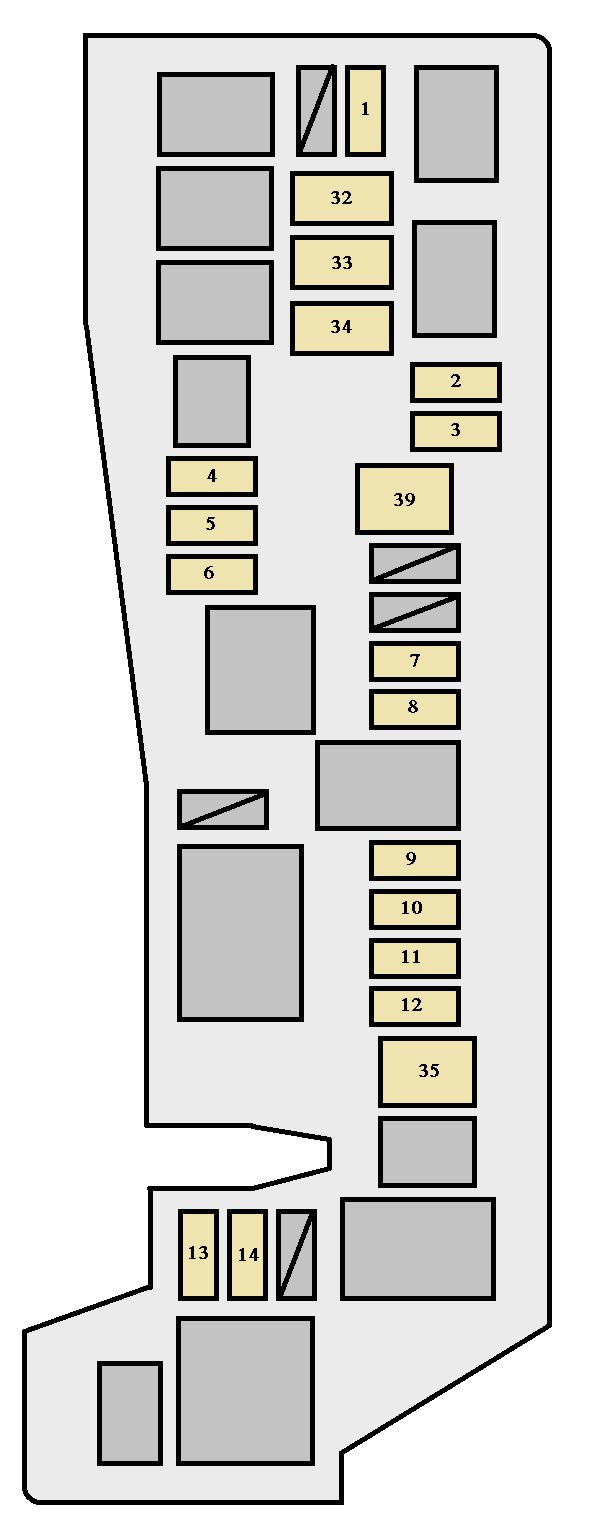
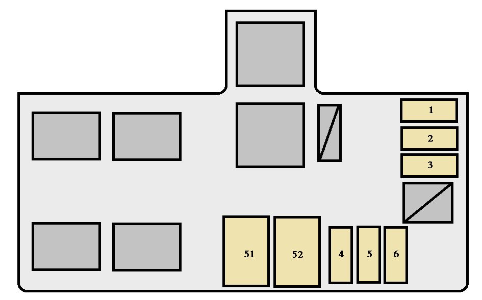
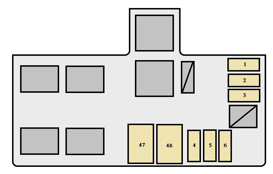
| 1 |
A/C RR |
40 |
Rear air conditioning system |
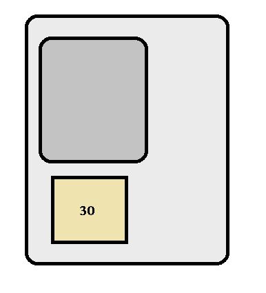
| 2 |
PTC HTR NO.3 |
30 |
PTC heater |
| 3 |
AIR SUS |
50 |
Air suspension system, AIR SUS NO.2 |
| 4 |
INV |
15 |
Inverter |
| 5 |
DEF |
30 |
Rear window defogger |
| 6 |
FOG RR |
7,5 |
Rear fog lights |
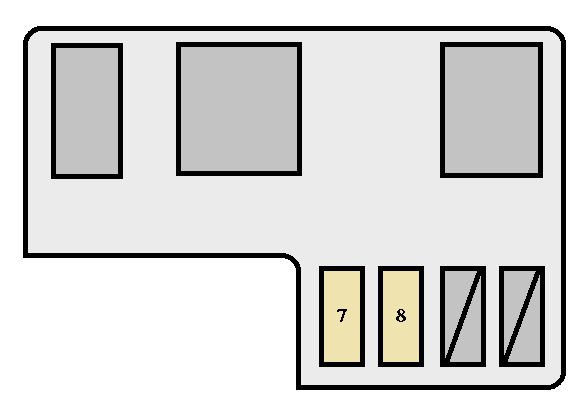
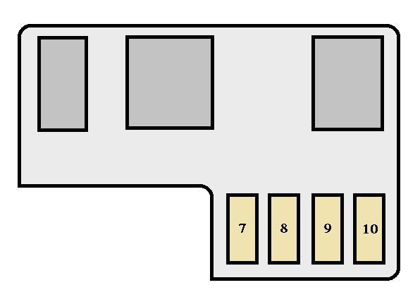
| 7 |
DEICER |
20 |
Windshield wiper deicer |
| 8 |
FUEL HTR*1 |
25 |
Fuel heater |
| AIR PMP HTR*2 |
10 |
Air pump heater |
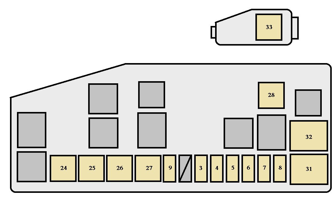
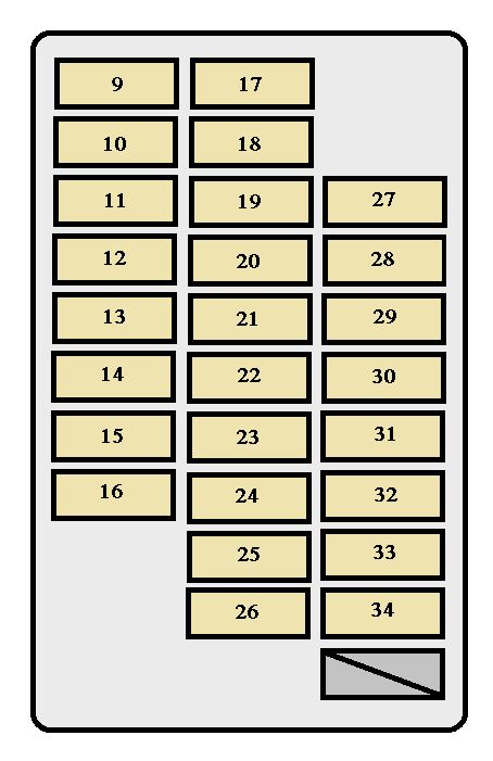
| 9 |
PTC HTR NO.2 |
30 |
PTC heater |
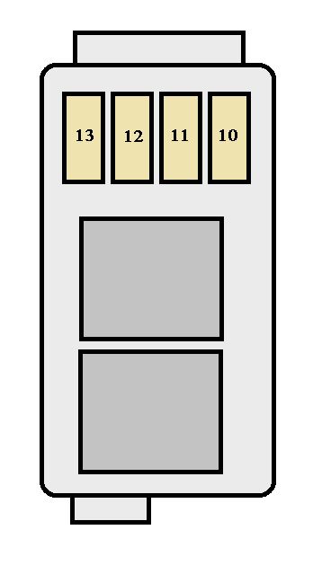
| 10 |
PTC HTR NO.1 |
50 |
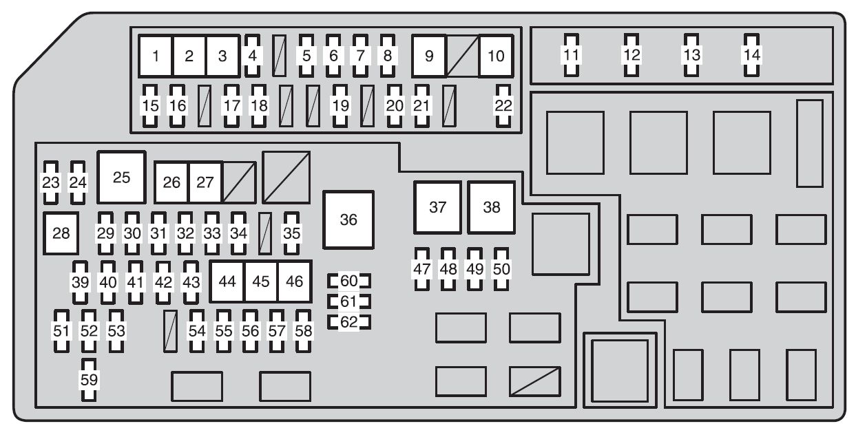
PTC heater |
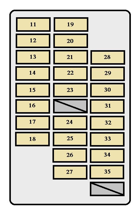
| 11 |
IG2 |
20 |
Injector, ignition, meter |
| 12 |
HORN |
10 |
Horn |
| 13 |
EFI |
25 |
EFI ECU, EDU, ECT ECU, fuel pump, A/F heater relay, FPC, EFI NO.2 |
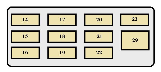
| 14 |
A/F*3 |
20 |
A/F SSR |
| EFI MAIN*9 |
20 |
A/F SSR, EFI No.2 |
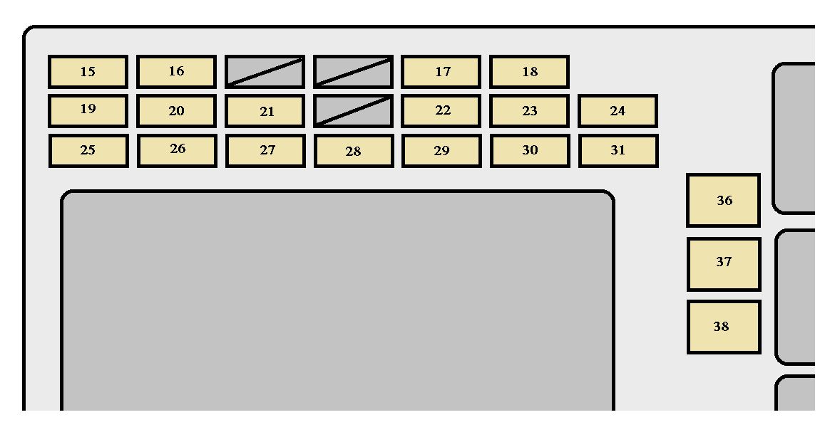
| 15 |
MIR HTR |
15 |
Mirror heater |
| 16 |
VISCUS*1 |
10 |
VISC heater |
| 17 |
FOLD SEAT LH |
30 |
Folding seat (left) |
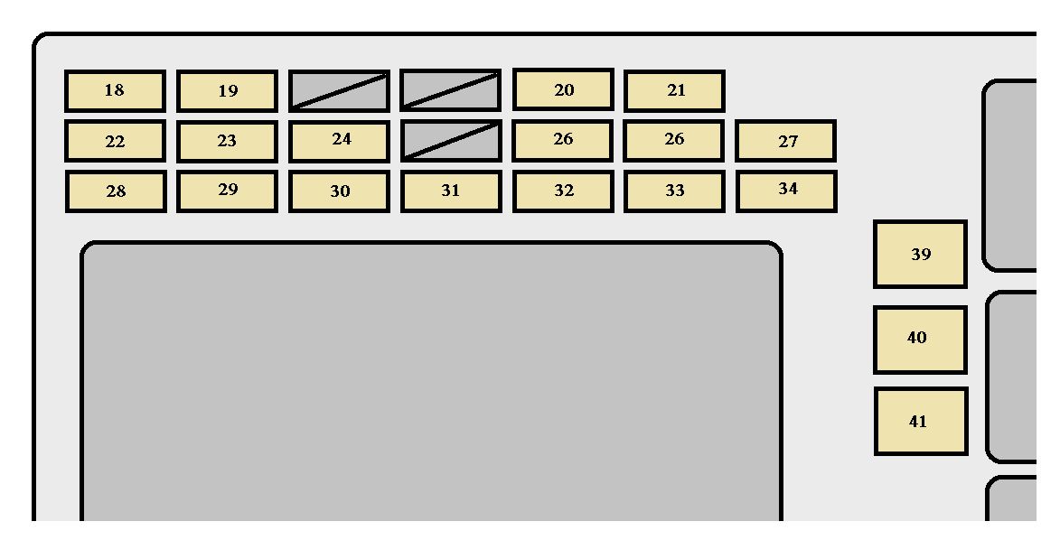
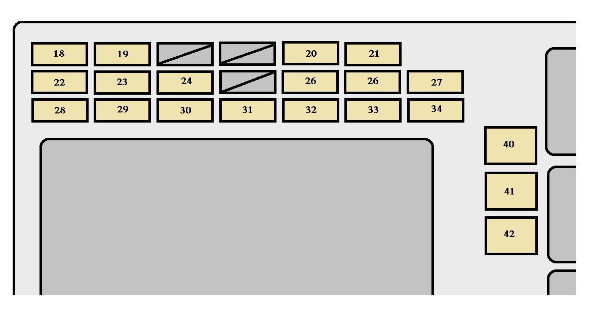
| 18 |
FOLD SEAT RH |
30 |
Folding seat (right) |
| 19 |
A/C COMP |
10 |
Air conditioning system |
| 20 |
CDS FAN |
20 |
Condenser fan |
| 21 |
STOP |
10 |
Emergency stop light relay, stop lights, high mount stop light, stop light switch, VSC/ABS ECU, towing, smart entry & start system, ECT ECU |
| 22 |
AIR SUS NO.2 |
7,5 |
AIR SUS ECU |
| 23 |
H-LP RH-HI |
15 |
Headlight high beam (right) |
| 24 |
H-LP LH-HI |
15 |
Headlight high beam (left) |
| 25 |
HTR |
50 |
Air conditioning system |
| 26 |
WIP WSH RR |
30 |
Rear window wipers and washer |
| 27 |
H-LP CLN |
30 |
Headlight cleaner |
| 28 |
ST |
30 A*3 |
STARTER MTR |
| 40 A*4 |
| 29 |
H-LP HI |
25 |
DIM relay, headlights |
| 30 |
ALT-S |
7,5 |
ALT |
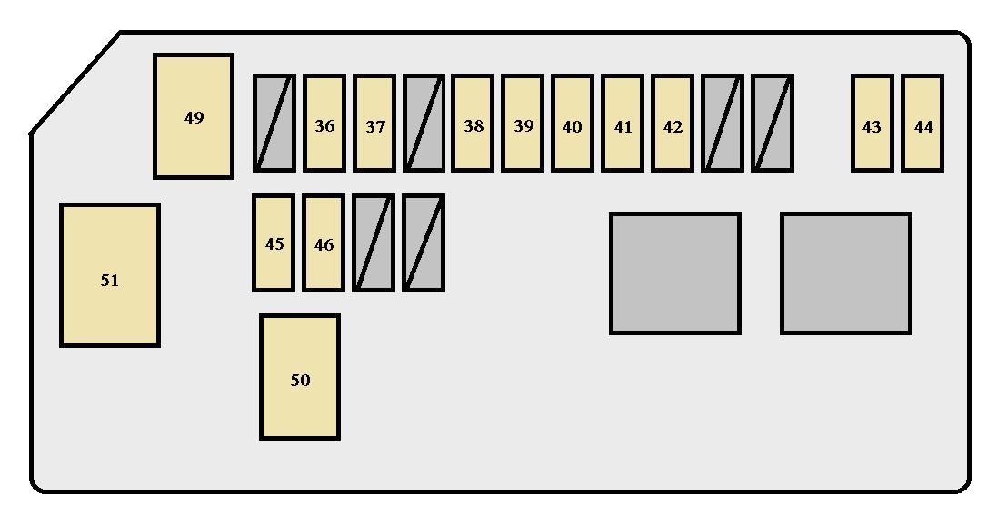
| 31 |
TURN & HAZ |
15 |
Front turn signal light, rear turn signal light, side turn signal light, meter turn signal light, trailer light |
| 32 |
D/L NO.1 |
25 |
Door lock motor, glass hatch opener |
| 33 |
ETCS*3 |
10 |
EFI ECU |
| EDU*9 |
20 |
Multiport fuel injection system/sequential multiport fuel injection system |
| 34 |
FUEL PMP*5 |
15 |
Fuel pump |
| 35 |
TOWING |
30 |
Towing |
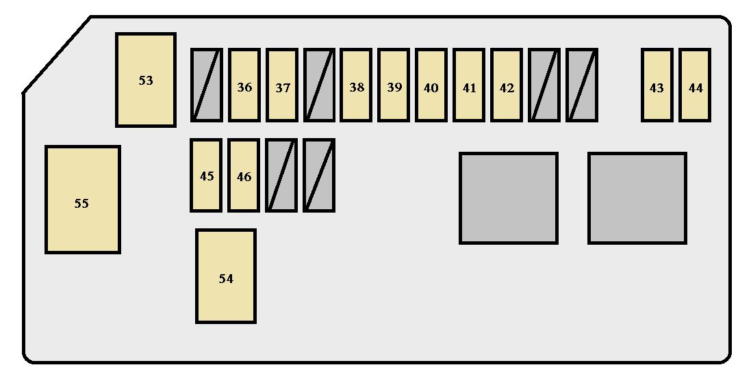
| 36 |
ALT |
140 A*6 |
Air conditioning system, AIR SUS, headlight cleaner, PTC heater, towing, folding seat, STOP, rear window defogger, MIR HTR, CDS FAN, RR FOG, DEICER, MG-CLT, J/B, INV, RR WIP, RR WSH |
| 120 A*3,7 |
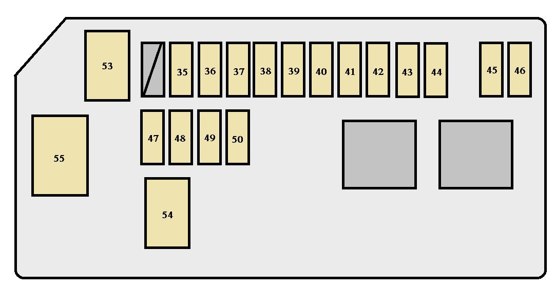
| 37 |
P/I-B |
80 |
Injector, ignition, meter, EFI, A/F heater, horn |
| 38 |
GLOW*4 |
80 |
Glow plug |
| 39 |
RAD NO.1 |
15 |
Audio system, navigation system, rear seat entertainment system |
| 40 |
AM2 |
7,5 |
Starter system |
| 41 |
RAD NO.2 |
10 |
Navigation system |
| 42 |
MAYDAY*8 |
7,5 |
Multiport fuel injection system/sequential multiport fuel injection system |
| 43 |
AMP |
30 |
Audio system |
| 44 |
ABS NO.1 |
50 |
ABS, VSC |
| 45 |
ABS NO.2 |
30 |
ABS, VSC |
| 46 |
AIR PMP*3 |
50 |
Air pump |
| 47 |
SECURITY |
10 |
Multiport fuel injection system/sequential multiport fuel injection system |
| 48 |
SMART |
7,5 |
Smart entry & start system |
| 49 |
STRG LOCK |
20 |
Steering lock system |
| 50 |
TOWING BRK |
30 |
Towing |
| 51 |
WIP RR |
15 |
Rear window wiper |
| 52 |
DOME |
10 |
Interior lights, personal lights, vanity lights, door courtesy lights, footwell lights, outer foot lights, overhead module |
| 53 |
ECU-B |
10 |
BODY ECU, meter, heater, steering sensor, wireless remote control, seat position memory, tilt and telescopic steering, multi display, smart entry & start system, folding seat, cool box, DSS#2 ECU, steering switch, D-module switch, overhead module |
| 54 |
H-LP RH-LO |
15 |
Headlight low beam (right), headlight leveling system |
| 55 |
H-LP LH-LO |
15 |
Headlight low beam (left) |
| 56 |
INJ |
10 |
Coil, injector, ignition, ECT ECU, noise filter |
| 57 |
EFI NO.2 |
10 |
O2 SSR, AFM, ACIS VSV, AI COMB, EYP VSV, AI DRIVER, EGR VRV, SWIRL VSV, SWIRL VSV 2, E/G CUT VSV, EGR COOL BYPASS VSV, D-SLOT ROTARY SOL, AI VSV RLY |
| 58 |
WIP FR NO.2 |
7,5 |
DSS#1 ECU |
| 59 |
WSH RR |
15 |
Rear window washer |
| 60 |
SPARE |
— |
Spare fuse |
| 61 |
SPARE |
— |
Spare fuse |
| 62 |
SPARE |
— |
Spare fuse |
*1: 1KD -FTV models only
*2: 1GR-FE models only
*3: Vehicles with gasoline engine
*4: Vehicles with diesel engine
*5: 1KD-FTV models with sub fuel tank only
*6: 1KD-FTV models with left hand drive vehicle
*7: 1KD-FTV models with right hand drive vehicle
*8: 1GR-FE models with right hand drive vehicle
*9: 1KD-FTV models (KDJ150R-GKFEYW, KDJ150R-GKAEYW, KDJ150L-GKFEYW, KDJ150L-GKAEYW, KDJ155R-GJFEYW, KDJ155R-GJAEYW, KDJ155L-GJFEYW and KDJ155L-GJAEYW models*10 except for Russia, Ukraine, Serbia, Montenegro, Makedonia and Croatia)
*10: The model code is indicated on the manufacturer’s label.) |