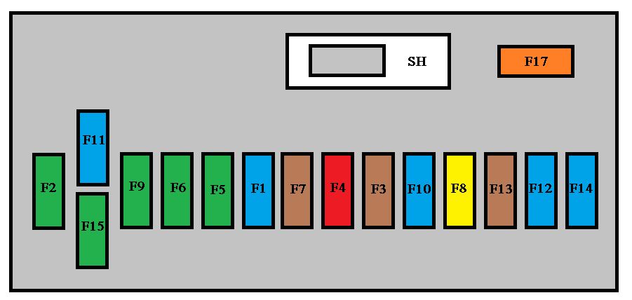
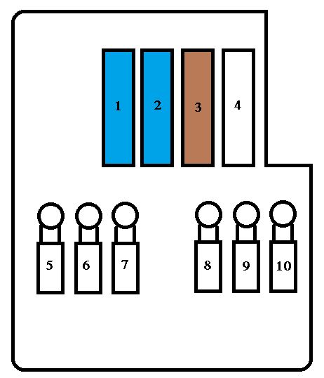
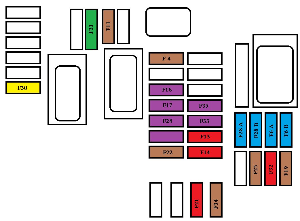
The fusebox is located in the lower left of the dashboard.
Peugeot 308 SW BL – fuse box – dashboard
Fuse
Ampere rating [A]
Functions
F1
15
Rear wiper
F2
30
Locking and deadlocking earth
F3
5
Airbags and pretensioners control unit
F4
10
Clutch pedal and dual-function brake switches, electrochromatic rear view mirror, air conditioning, steering wheel angle sensor, automatic gearbox, switching and protection unit
F5
30
Front one-touch electric windows, folding mirrors supply, panoramic sunroof blind
F6
30
Rear one-touch electric windows, trailer fusebox
F7
5
Front and rear courtesy lamps, map reading lamps, rear reading lampd, sun visor illumination, glove box illumination, torch
F8
20
Audio equipment, audio/telephone, CD changer, multifunction screen, tyre under-infl ation detection
F9
30
Front 12 V socket
F10
15
Steering mounted controls, alarm siren, alarm control unit
F11
15
Low current ignition switch
F12
15
Instrument panel, seat belt and passenger’s front airbag warning lamps display, air conditioning, driver’s seat memory unit, 2nd row rear seat switches, driving school module
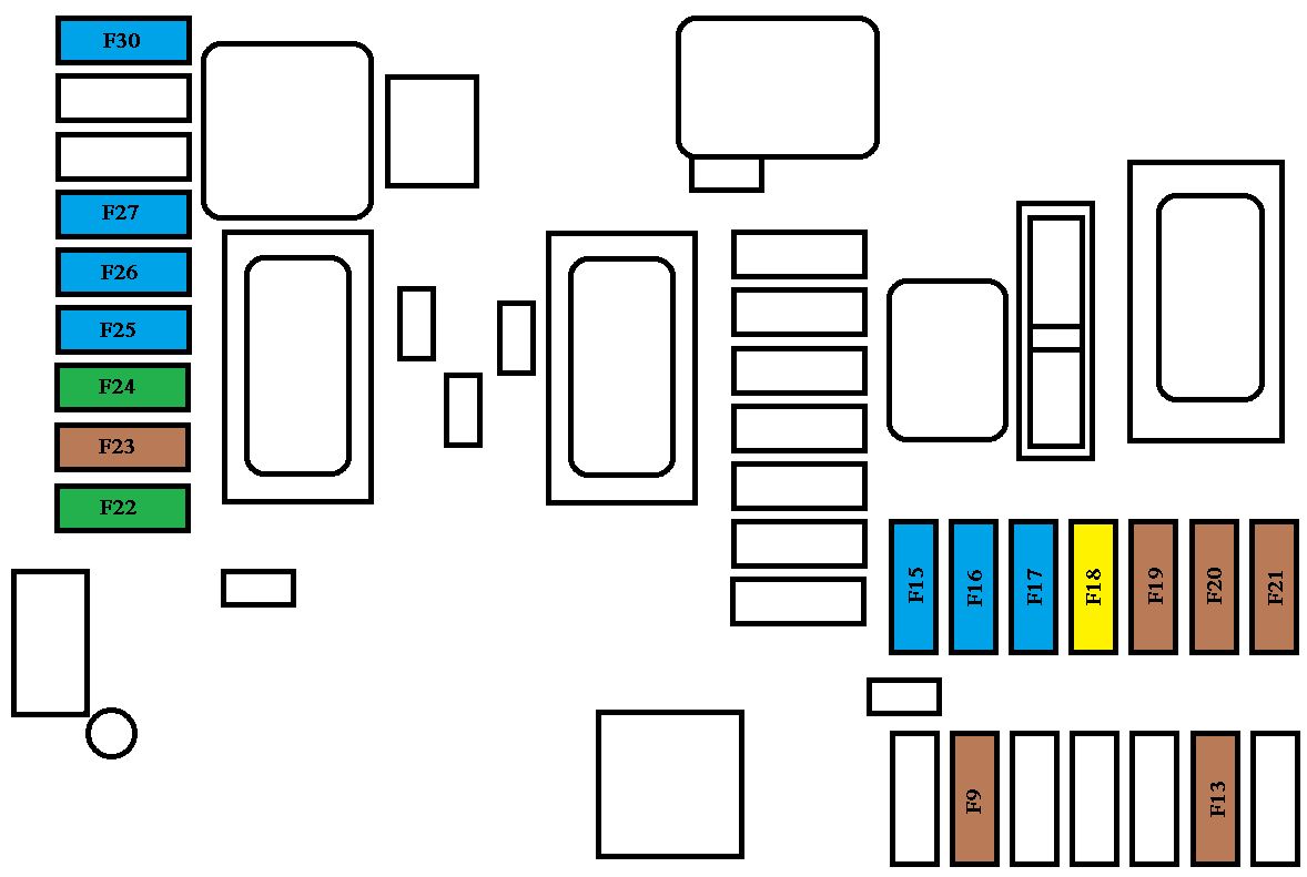
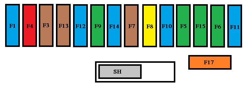
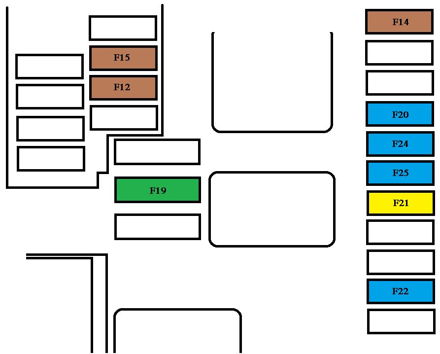
The fuse box is placed in the lower section of the fascia (left-hand side).
Peugeot 308 SW BL – fuse box – dashboard
Fuse
Ampere rating [A]
Functions
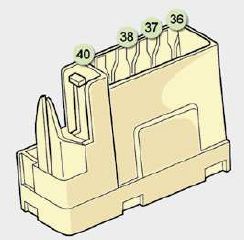
F36
30
Not used
F37
5
Trailer fuse box
F38
30
Driver’s seat memory unit
F39
—
Trailer fuse box supply
F40
30
Hi-Fi amplifier, passenger’s seat memory unit
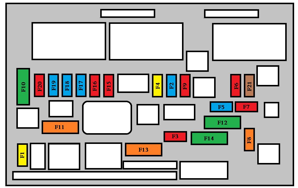
Fuse
Ampere rating [A]
Functions
F1
15
Rear wiper
F2
—
Not used
F3
5
Air bags and pretensioners control unit
F4
10
Clutch pedal and dual-function brake switches, electrochromatic interior mirror, air conditioning, steering wheel angle sensor, automatic gearbox, switching and protection unit
F5
30
Front one-touch electric windows, folding mirrors supply
F6
30
Rear one-touch electric windows, exterior door opening controls
F7
5
Front and rear courtesy lights, map reading lights, rear reading lights, sun visor lighting, glove box lighting, portable lamp
F8
20
Audio equipment, audio/telephone, CD changer, multifunction display, tyre under-infl ation detection
F9
30
Front 12 V socket, lighter
F10
15
Steering wheel controls, alarm siren, alarm control unit
F11
15
Low current ignition switch
F12
15
Instrument panel, seat belt and passenger’s front air bag warning lights display, air conditioning, driver’s seat memory unit, 2nd row rear seat switches, driving school module
F13
5
Engine fuse box, air bags, piloted manual gearbox gear lever
F14
15
Multifunction display, amplifi er, hands-free kit, rain/brightness sensor, parking assistance control unit, trailer fuse box, lane departure warning system
F15
30
Locking and deadlocking
F17
40
Rear screen and exterior mirrors de-icing
SH
—
PARC shunt
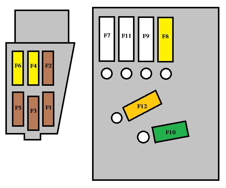
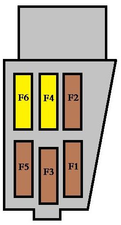
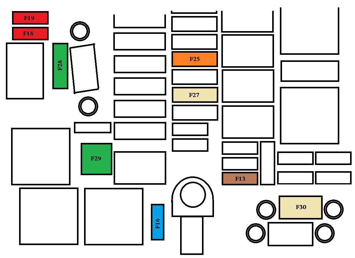
Engine compartment fuses
The fuse box is placed in the engine compartment near the battery (left-hand side).
Peugeot 308 SW BL – fuse box – engine compartment
Fuse
Ampere rating [A]
Functions
F1
20
Engine control unit supply, injection pump and EGR solenoid valves (2 l HDI 16V), injectors (2 l HDI 16V)
F2
15
Horn
F3
10
Front wash-wipe
F4
20
Headlamp wash
F5
15
Purge canister, turbine discharge and Turbo pressure regulation solenoid valves (1.6 l THP 16V), oil vapour heater (1.6 l THP 16V)
F6
10
Vehicle speed sensor, ABS/ESP control unit
F7
10
Power steering control unit, automatic gearbox, engine coolant level detector