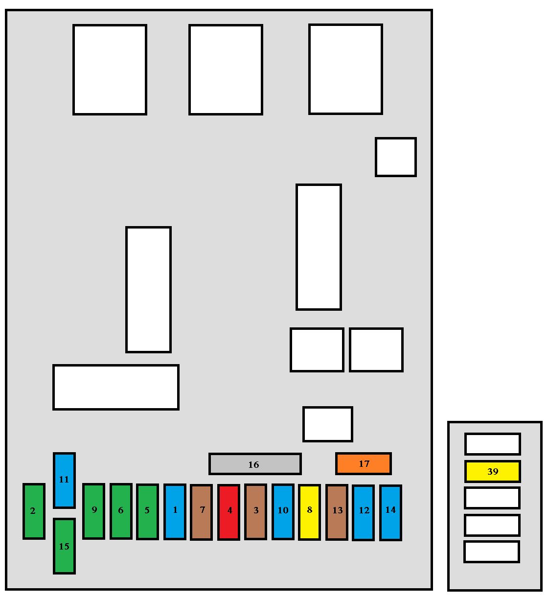
Engine control unit and fan assembly high speed relay supply
2
15
Horn
3
10
Front and rear wash-wipe
4
10
Headlamp wash
5
15
Fuel pump and purge canister solenoid valve (2 litre petrol)
6
10
Four speed automatic gearbox control unit, automatic gearbox lever locking control, push control switch, fan assembly high speed relay, right and left xenon headlamps
7
10
ABS/ESP control unit, power steering electro-pump unit control unit
8
25
Starter control
9
10
Additional heating unit (Diesel), coolant level switch
10
30
Engine control unit actuators (ignition coil, solenoid valves, oxygen sensors, control units, injectors, heaters), purge canister solenoid valve (1.4 litre petrol and 1.6 litre petrol)
11
40
Air conditioning blower
12
30
Windscreen wipers low/high speed
13
40
Built-in systems interface supply (ignition positive)
14
30
Air pump (2 litre petrol)
15*
10
Right main beam headlamp
16*
15
Left main beam headlamp
17*
15
Left dipped headlamp
18*
15
Right dipped headlamp
41
15
Six speed automatic gearbox control unit
Maxi – fuse table
Fuse
Ampere rating [A]
Functions
MF1
30
200 W fan unit
50
400 W and 460 W fan unit
MF2
30
ABS/ESP pump
MF3
30
ABS/ESP solenoid valves
MF4
60
Built-in Systems Interface supply
MF5
70
Built-in Systems Interface supply
MF6
20
Passenger compartment fuse box
MF8
70
Power steering electro-pump unit
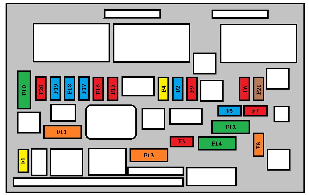
WARNING: Terminal and harness assignments for individual connectors will vary depending on vehicle equipment level, model, and market.
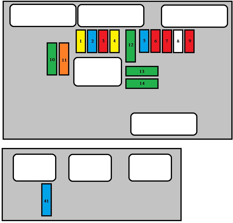
Automatic gearbox reversing lights switch – Automatic gearbox starting inhibitor relay control – Manual gearbox reversing lights switch – Vehicle speed sensor – Pre-heat control unit – Water in diesel sensor – DW air flow sensor
2
15
Canister solenoid valve – Fuel pump
3
10
Power steering control unit – ABS or ESP control unit
4
10
Injection control unit – Fan unit relay control – Additional heating relay control – Automatic gearbox control unit – Automatic gearbox sequential control – Automatic gearbox shiftlock relay.
5
15
Particulate emission filter control unit
6
15
Front fog lamps
7
20
Headlamp wash pump
8
20
Fan unit relay control – Injection control unit supply
9
15
Left dipped beam
10
15
Right dipped beam
11
10
Left main beam
12
10
Right main beam
13
15
Horn
14
10
Front and rear headlamps wash pump
15
30
Oxygen sensors – Exhaust gas recirculation solenoid valve – Ignition coil – Diesel high pressure regulator – Injectors supply (petrol)
16
40
Petrol engine air pump with automatic gearbox
17
30
Low/high speed front wiper
18
40
Air conditioning blower
Maxi – fuse table
Fuse
Ampere rating [A]
Functions
1
30
Fan unit
2
30
ESP/ABS pump motor
3
30
ESP/ABS solenoid valves
4
60
Built-in Systems Interface supply
5
70
Built-in Systems Interface supply
6
20
Heated seats
7
30
Ignition switch, power
8
70
Power steering electro-pump unit
WARNING: Terminal and harness assignments for individual connectors will vary depending on vehicle equipment level, model, and market.
Engine control unit and fan assembly high speed relay supply
2
15
Horn
3
10
Front and rear wash-wipe
4
10
Headlamp wash
5
15
Fuel pump and purge canister solenoid valve (2 litre petrol)
6
10
Four speed automatic gearbox control unit, automatic gearbox lever locking control, push control switch, fan assembly high speed relay, right and left xenon headlamps
7
10
ABS/ESP control unit, power steering electro-pump unit control unit
8
25
Starter control
9
10
Additional heating unit (Diesel), coolant level switch
10
30
Engine control unit actuators (ignition coil, solenoid valves, oxygen sensors, control units, injectors, heaters), purge canister solenoid valve (1.4 litre petrol and 1.6 litre petrol)
11
40
Air conditioning blower
12
30
Windscreen wipers low/high speed
13
40
Built-in systems interface supply (ignition positive)
14
30
Air pump (2 litre petrol)
15*
10
Right main beam headlamp
16*
15
Left main beam headlamp
17*
15
Left dipped headlamp
18*
15
Right dipped headlamp
41
15
Six speed automatic gearbox control unit
Maxi – fuse table
Fuse
Ampere rating [A]
Functions
MF1
30
200 W fan unit
50
400 W and 460 W fan unit
MF2
30
ABS/ESP pump
MF3
30
ABS/ESP solenoid valves
MF4
60
Built-in Systems Interface supply
MF5
70
Built-in Systems Interface supply
MF6
20
Passenger compartment fuse box
MF8
70
Power steering electro-pump unit
WARNING: Terminal and harness assignments for individual connectors will vary depending on vehicle equipment level, model, and market.
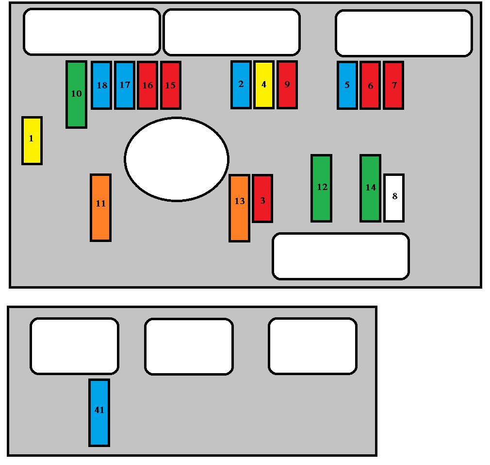
Automatic gearbox reversing lights switch – Automatic gearbox starting inhibitor relay control – Manual gearbox reversing lights switch – Vehicle speed sensor – Pre-heat control unit – Water in diesel sensor – DW air flow sensor
2
15
Canister solenoid valve – Fuel pump
3
10
Power steering control unit – ABS or ESP control unit
4
10
Injection control unit – Fan unit relay control – Additional heating relay control – Automatic gearbox control unit – Automatic gearbox sequential control – Automatic gearbox shiftlock relay.
5
15
Particulate emission filter control unit
6
15
Front fog lamps
7
20
Headlamp wash pump
8
20
Fan unit relay control – Injection control unit supply
9
15
Left dipped beam
10
15
Right dipped beam
11
10
Left main beam
12
10
Right main beam
13
15
Horn
14
10
Front and rear headlamps wash pump
15
30
Oxygen sensors – Exhaust gas recirculation solenoid valve – Ignition coil – Diesel high pressure regulator – Injectors supply (petrol)
16
40
Petrol engine air pump with automatic gearbox
17
30
Low/high speed front wiper
18
40
Air conditioning blower
Maxi – fuse table
Fuse
Ampere rating [A]
Functions
1
30
Fan unit
2
30
ESP/ABS pump motor
3
30
ESP/ABS solenoid valves
4
60
Built-in Systems Interface supply
5
70
Built-in Systems Interface supply
6
20
Heated seats
7
30
Ignition switch, power
8
70
Power steering electro-pump unit
WARNING: Terminal and harness assignments for individual connectors will vary depending on vehicle equipment level, model, and market.
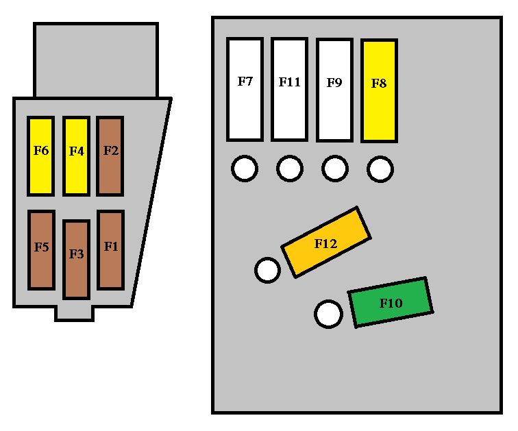
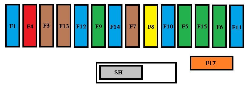
The fuse box is placed in the lower section of the fascia (left-hand side).
Peugeot 3008 Hybrid – fuse box – fascia
Fuse
Ampere rating [A]
Functions
F1
15
Rear wiper
F2
—
Not used
F3
5
Air bags control unit
F4
10
Electrochromatic rear view mirror, air conditioning, switching and protection unit, rear multimedia, traction battery control unit.
F5
30
Front one-touch electric windows
F6
30
Rear one-touch electric windows
F7
5
Front and rear courtesy lamps, map reading lamps, rear reading lamps, sun visor lighting, glove box lighting, centre armrest lighting, boot 12 V relay control.
F8
20
Audio equipment, audio/telephone, CD changer, multifunction screen, tyre under-inflation detection, alarm siren, alarm control unit, telematic unit, service module (with Peugeot Connect Media)
F9
30
Front 12 V socket, cigarette lighter, rear 12 V
socket
F10
15
Steering mounted controls
F11
15
Low current ignition switch
F12
15
Trailer presence, rain/sunshine sensor, supply for fuses F32, F34, F35
F13
5
Engine fusebox, airbag control unit
F14
15
Instrument panel, instrument panel screen, supply for fuse F33
F15
30
Locking and deadlocking
F17
40
Heated rear screen, supply for fuse F30
SH
—
PARC shunt
Fuse
Ampere rating [A]
Functions
F29
—
Not used
F30
5
Heated exterior mirrors
F31
30
Boot 12 V socket
F32
5
Piloted manual gearbox gear lever
F33
10
Head-up display, Bluetooth system, air conditioning, retractable screen
F34
5
Seat belt warning lamps display
F35
10
Parking sensors
F36
10
Front heated seats
F37
20
Hi-Fi amplifier
F38
30
Traction battery control unit
F39
20
Panoramic sunroof blind
F40
10
Trailer interface, driver’s door control panel
Engine compartment fuses
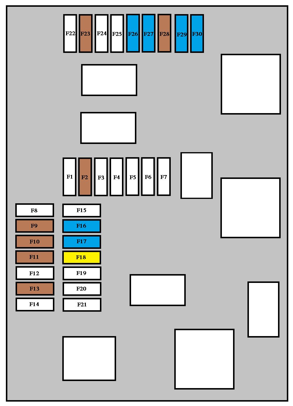
The fuse box is placed in the engine compartment near the battery (left-hand side).
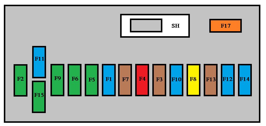
The fuse box is placed in the lower section of the fascia (left-hand side).
Peugeot 3008 – fuse box – fascia
Fuse
Ampere rating [A]
Functions
F1
15
Rear wiper
F2
—
Not used
F3
5
Air bags control unit
F4
10
Electrochromatic interior mirror, air conditioning, switching and protection unit, rear multimedia
F5
30
Front one-touch electric windows
F6
30
Rear one-touch electric windows
F7
5
Front and rear courtesy lights, map reading lights, rear reading lights, sun visor lighting, glove box lighting, centre armrest lighting, boot 12 V relay control
F8
20
Audio equipment, audio/telephone, CD changer, multifunction display, tyre under-infl ation detection, alarm siren, alarm control unit, telematic unit, service module (with PC Com 3D)
F9
30
Front 12 V socket, lighter, rear 12 V socket.
F10
15
Steering wheel controls
F11
15
Low current ignition switch
F12
15
Trailer presence, rain/brightness sensor, supply for fuses F32, F34, F35
F13
5
Engine fuse box, air bags control unit
F14
15
Instrument panel, instrument panel display, supply for fuse F33
F15
30
Locking and deadlocking
F17
40
Rear screen de-icing, supply for fuse F30
SH
—
PARC shunt
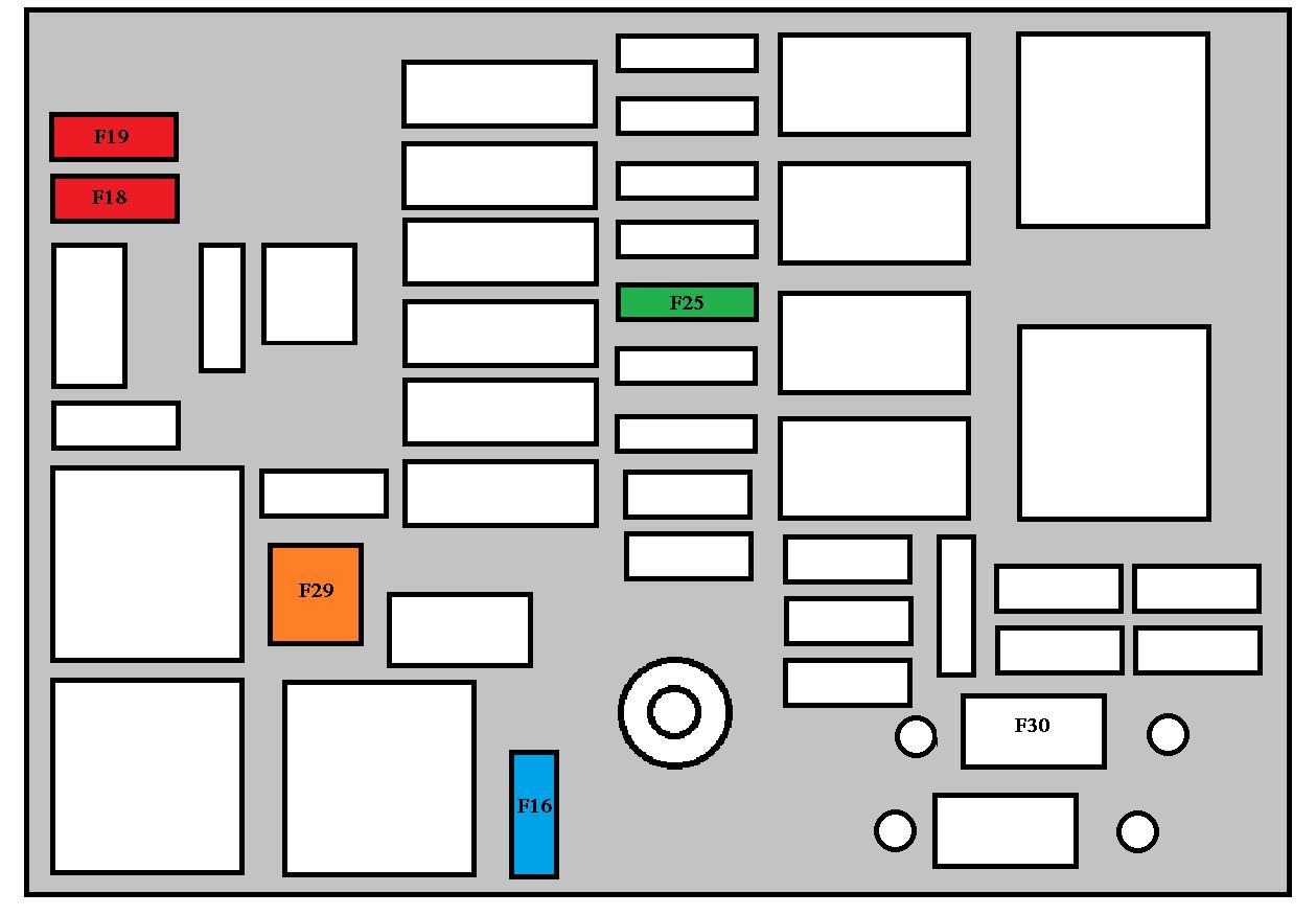
Fuse
Ampere rating [A]
Functions
F29
30
Boot 12 V socket
F30
5
Heated exterior mirrors
F31
15
Refrigerator socket
F32
5
Piloted manual gearbox gear lever
F33
10
Head up display, hands-free kit, air conditioning
F34
5
Seat belt warning lights display
F35
10
Parking assistance, Hi-Fi amplifier authorisation
F36
10
Trailer fuse box control unit, driver’s door control pad
F37
20
Hi-Fi amplifier
F38
30
Driver’s electric seat
F39
20
Panoramic glass roof shutter
F40
—
Not used
Engine compartment fuses
The fuse box is placed in the engine compartment near the battery (left-hand side).
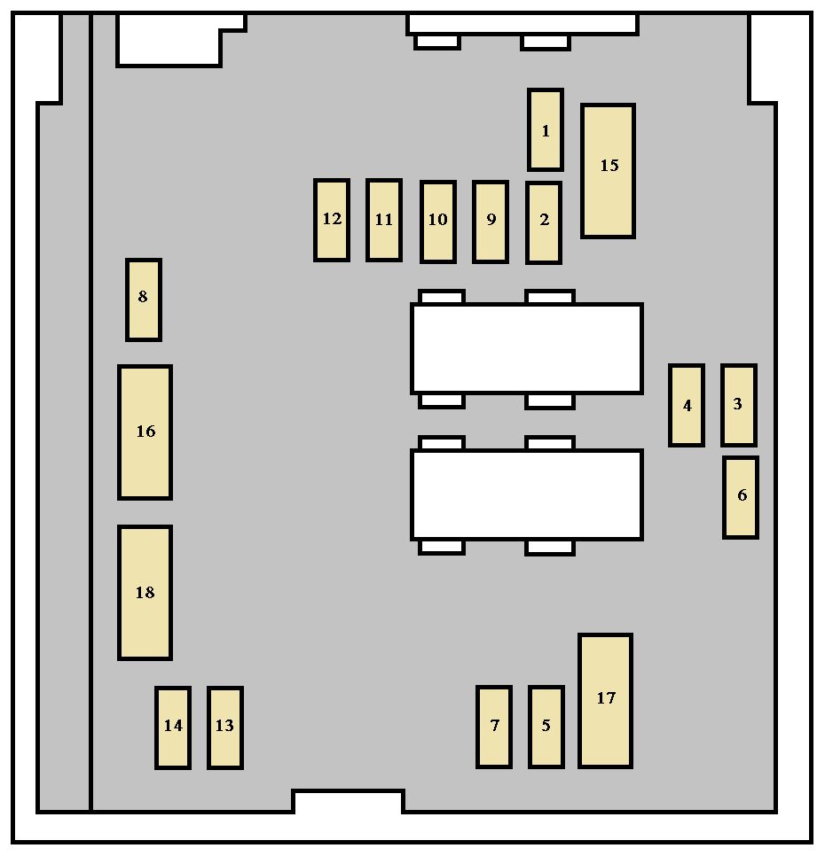
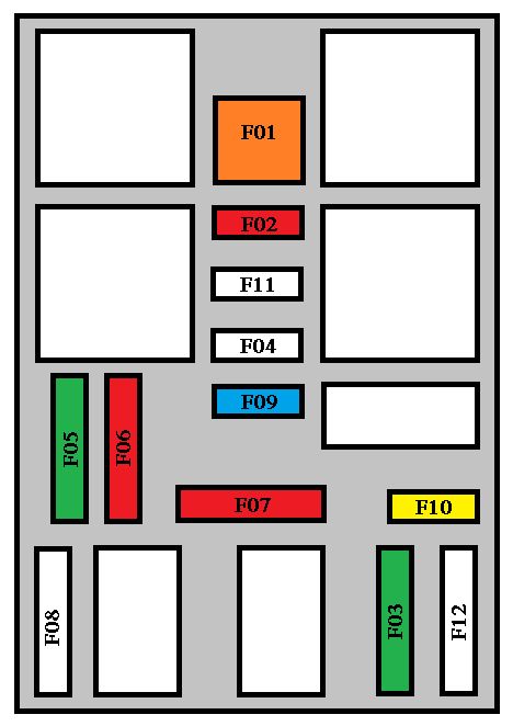
Peugeot 3008 – fuse box – engine compartment
Fuse
Ampere rating [A]
Functions
F1
20
Engine control unit supply, injection pump and EGR solenoid valves (2 l HDI 16V), injectors (2 l HDI 16V)
F2
15
Horn
F3
10
Front/rear wash-wipe
F4
10
Daytime lights
F5
15
Purge canister, turbine discharge and Turbo pressure regulation solenoid valves (1.6 l THP 16V), oil vapour heater (1.6 l THP 16V), diesel heater (1.6 l HDI 16V)
F6
10
Diagnostic socket, directional headlamps, particle emission fi lter pump (Diesel), “distance alert” engine coolant level detector, mirror adjustment control
F7
10
Power steering control unit, automatic gearbox, directional headlamps height adjustment motor
Instrument panel, seat belt warning lights bar, headlamp adjustment, air conditioning, audio equipment, hands-free kit, rear parking assistance control unit
F15
30
Locking and deadlocking
F17
40
Rear screen and exterior mirrors de-icing
SH
—
PARC shunt
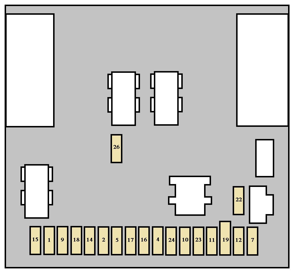
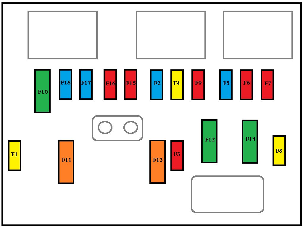
Engine compartment fuses
The fuse box is placed in the engine compartment, near the battery (lefthand side).
Peugeot 207 CC -fuse box – engine compartment
Fuse
Ampere rating [A]
Functions
F1
20
Engine control unit and fan assembly control relay supply, timing and canister solenoid valves (1.6 l 16V THP), air flow sensor (Diesel), injection pump (Diesel), water in diesel sensor (Diesel), EGR solenoid valves, air heating (Diesel).
F2
15
Horn
F3
10
Front and rear wash-wipe
F4
20
Headlamp wash
F5
15
Fuel pump (petrol), Turbo solenoid valves (1.6 l 16V THP)
F6
10
Vehicle speed sensor, automatic gearbox
F7
10
Electric power steering, directional headlamps, directional headlamps control relay, switching and protection unit (Diesel)
F8
25
Starter control
F9
10
ABS/ESP control unit, brake pedal switch
F10
30
Engine control unit actuators (petrol: ignition coils,
solenoid valves, oxygen sensors, injectors, heaters,
controlled thermostat) (Diesel: solenoid valves,
heaters)
F11
40
Air conditioning blower
F12
30
Windscreen wipers Low/High speed
F13
40
Built-in systems interface supply (ignition positive)
F14
30
Diesel heater (Diesel)
F15
10
Left main beam headlamp
F16
10
Right main beam headlamp
F17
15
Left dipped beam headlamp
F18
15
Right dipped beam headlamp
Fuse
Ampere rating [A]
Functions
BOX 1
MF1
70
Fan assembly
MF2
20/30
ABS/ESP pump
MF3
20/30
ABS/ESP solenoid valves
MF4
60
Built-in systems interface supply
MF5
60
Built-in systems interface supply
MF6
—
Additional fan assembly (1.6 l 16V THP)
MF7
80
Passenger compartment fuse box
BOX 2
MF8
30
Not used
MF9
80
Heating unit (Diesel)
MF10
80
Electric power steering
MF11
40
Valvetronic electric motor (1.6 l 16V THP)
WARNING: Terminal and harness assignments for individual connectors will vary depending on vehicle equipment level, model, and market.