Peugeot 207 (2006 – 2008) – fuse box diagram
Year of production: 2006, 2007, 2008
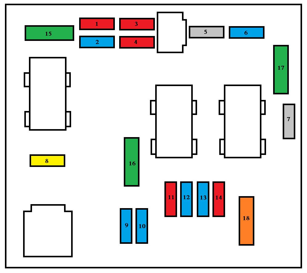
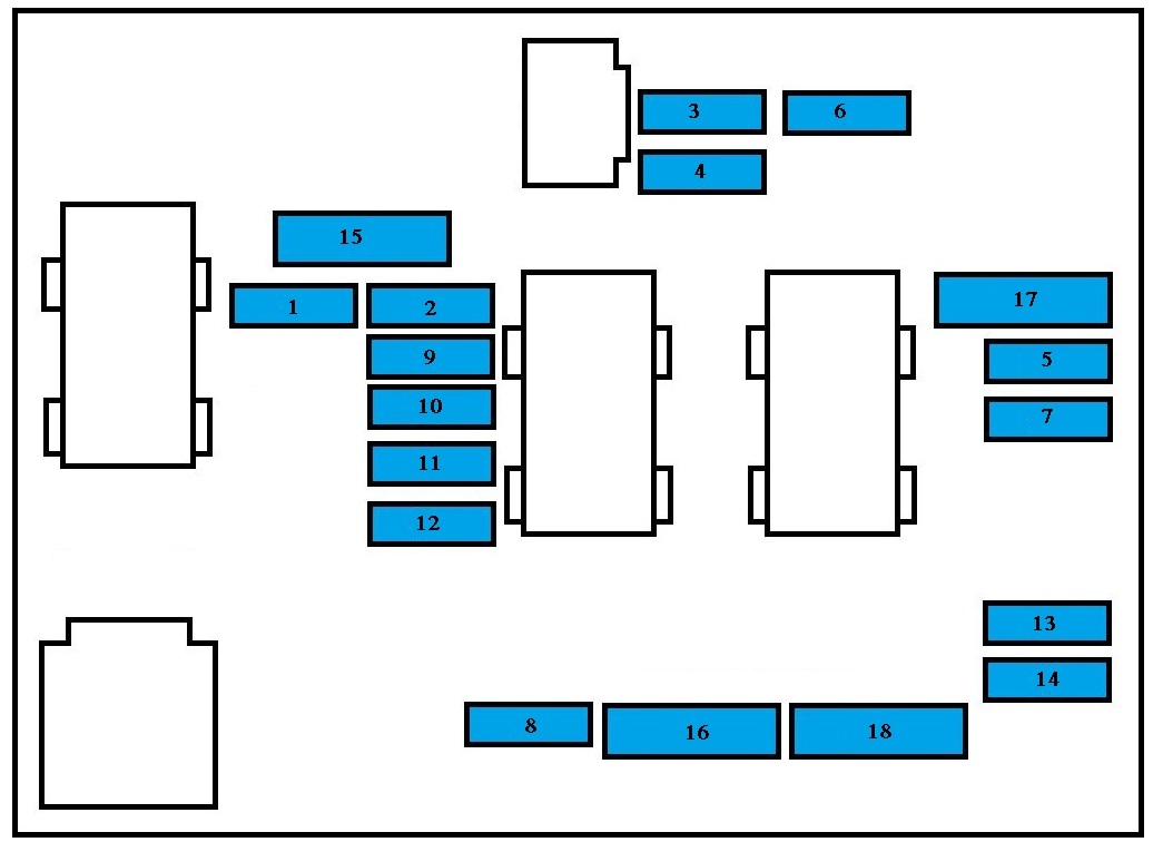
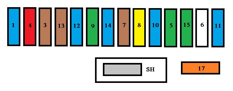
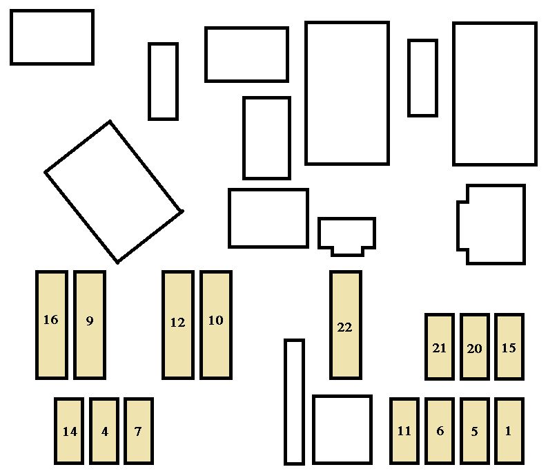
Dashboard fuses
The fusebox is located in the lower part of the dashboard (left-hand side).
| Fuse | Ampere rating [A] | Functions |
| G39 | 20 | Hi-Fi amplifier |
| G40 | — | Not used |
| Fuse | Ampere rating [A] | Functions |
| F1 | 15 | Rear wiper |
| F2 | — | Not used |
| F3 | 5 | Airbag and pre-tensioner control unit |
| F4 | 10 | Clutch pedal switch, diagnostic socket, electrochromatic rear view mirror, air conditioning, steering wheel angle sensor, particle emission filter pump (Diesel). |
| F5 | 30 | Electric windows, rear electric windows, sunroof |
| F6 | 30 | Front electric windows, folding mirrors supply |
| F7 | 5 | Front and rear courtesy lights, map reading lights, sun visor lighting, glove box lighting, clock |
| F8 | 20 | Audio equipment, audio/telephone, CD changer, multifunction display, clock, steering wheel controls, tyre under-inflation detection, trailer fuse box. |
| F9 | 30 | Front 12 V socket |
| F10 | 15 | Alarm siren, alarm control unit, directional headlamps |
| F11 | 15 | Diagnostic socket, low current ignition switch |
| F12 | 15 | Rain/brightness sensor, amplifier, trailer fuse box, driving school module |
| F13 | 5 | Engine fuse box, ABS relay, “2 Tronic” gearbox selector lever, dual-function brake switch |
| F14 | 15 | Instrument panel, seat belt warning lights bar, headlamp adjustment, air conditioning, hands-free kit, rear parking assistance control unit, air bags |
| F15 | 30 | Locking and deadlocking |
| F17 | 40 | Rear screen and exterior mirrors de-icing |
| SH | — | PARC shunt |
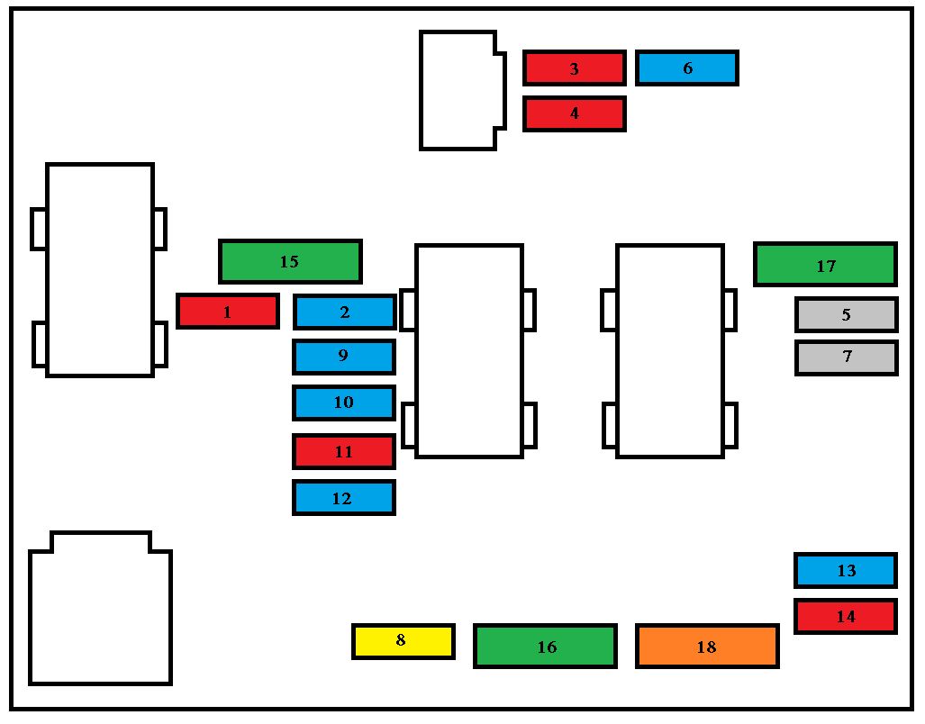
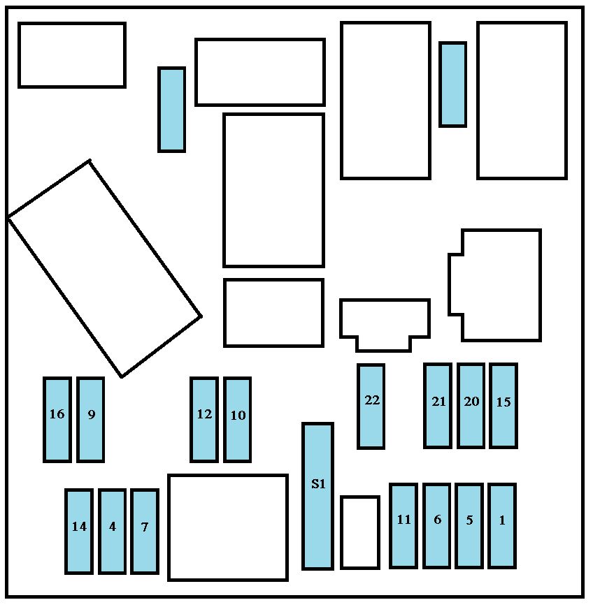
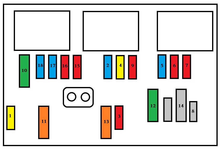
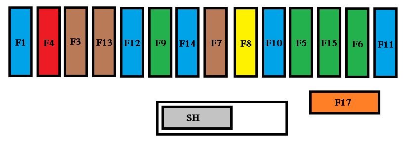
Engine compartment fuses
The fuse box is placed in the engine compartment, near the battery (lefthand side).
| Fuse | Ampere rating [A] | Functions |
| F1 | 20 | Engine control unit and fan assembly control relay supply, air flow sensor (Diesel), injection pump (Diesel), water in diesel sensor (Diesel), EGR solenoid valves, air heating (Diesel) |
| F2 | 15 | Horn |
| F3 | 10 | Front and rear wash-wipe |
| F4 | 20 | Headlamp wash |
| F5 | 15 | Fuel pump (petrol) |
| F6 | 10 | Vehicle speed sensor |
| F7 | 10 | Electric power steering, directional headlamps, directional headlamps control relay, engine coolant level detector (Diesel), switching and protection unit (Diesel) |
| F8 | 25 | Starter control |
| F9 | 10 | ABS/ESP control unit, brake pedal switch |
| F10 | 30 | Engine control unit actuators (petrol: ignition coils, solenoid valves, oxygen sensors, injectors, heaters, controlled thermostat) (Diesel: solenoid valves, heaters). |
| F11 | 40 | Air conditioning blower |
| F12 | 30 | Windscreen wipers Low/High speed |
| F13 | 40 | Built-in systems interface supply (ignition positive) |
| F14 | 30 | Diesel heater (Diesel) |
| F15 | 10 | Left main beam headlamp |
| F16 | 10 | Right main beam headlamp |
| F17 | 15 | Left dipped beam headlamp |
| F18 | 15 | Right dipped beam headlamp |
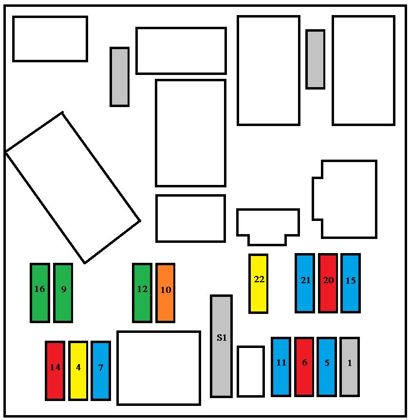
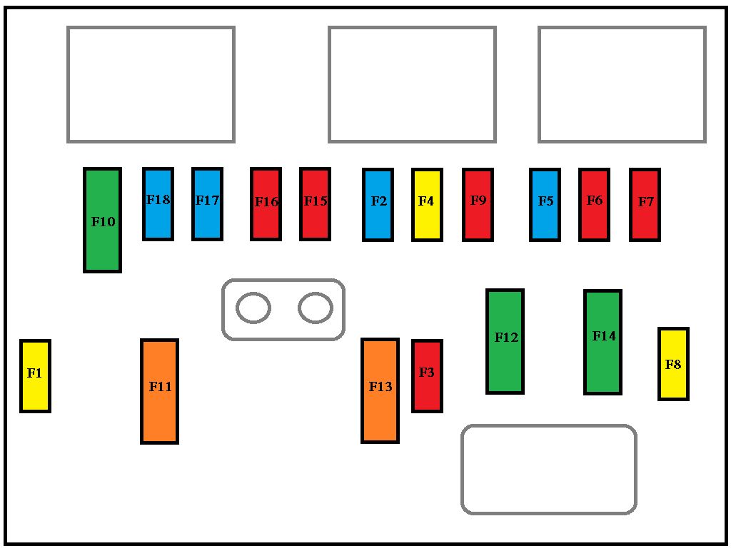
| Fuse | Ampere rating [A] | Functions | |
| BOX 1 | MF1 | 70 | Fan assembly |
| MF2 | 20/30 | ABS/ESP pump | |
| MF3 | 20/30 | ABS/ESP solenoid valves | |
| MF4 | 60 | Built-in systems interface supply | |
| MF5 | 60 | Built-in systems interface supply | |
| MF6 | — | Not used | |
| MF7 | 80 | Passenger compartment fuse box | |
| BOX 2 | MF8 | 30 | “2 Tronic” gearbox ECU |
| MF9 | 80 | Heating unit (Diesel) | |
| MF10 | 80 | Electric power steering |
WARNING: Terminal and harness assignments for individual connectors will vary depending on vehicle equipment level, model, and market.