Peugeot 106 (1996 – 2003) – fuse box diagram

Peugeot 106 (1996 – 2003) – fuse box diagram

Year of production: 1996, 1997, 1998, 1999, 2000, 2001, 2002, 2003
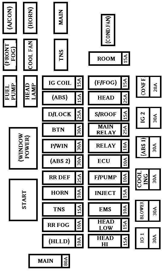
Engine compartment

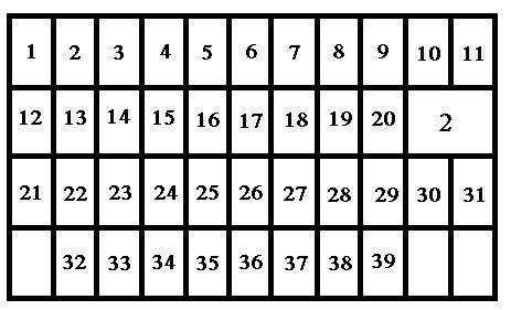
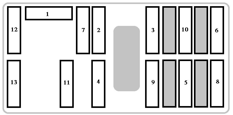
16 fuse box (engine compartment)

The 16 fuse boxes and maxi fuse boxes are located under the bonnet.
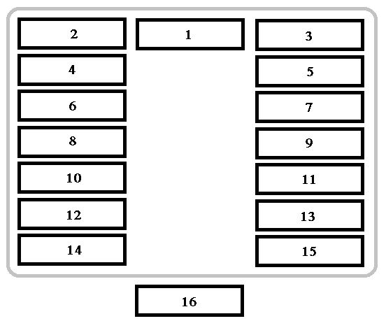
Peugeot 106 DAG - fuse - box - engine compartment
Peugeot 106 – fuse – box – engine compartment
Fuse Ampere rating [A] Functions
1 Not used
2 30 Anti-lock braking system
3 25 Engine cooling
4 20 Anti-lock braking system
5 25 Fan unit
6 20 Additional driving lamps
7 Not used
8 Not used
9 10 Fuel pump
10 Not used
11 10 Oxygen sensor
12 10 Left-hand main beam
13 10 Right-hand main beam
14 10 Left-hand dipped beam
15 10 Right-hand dipped beam
16 30 Pulsair pump

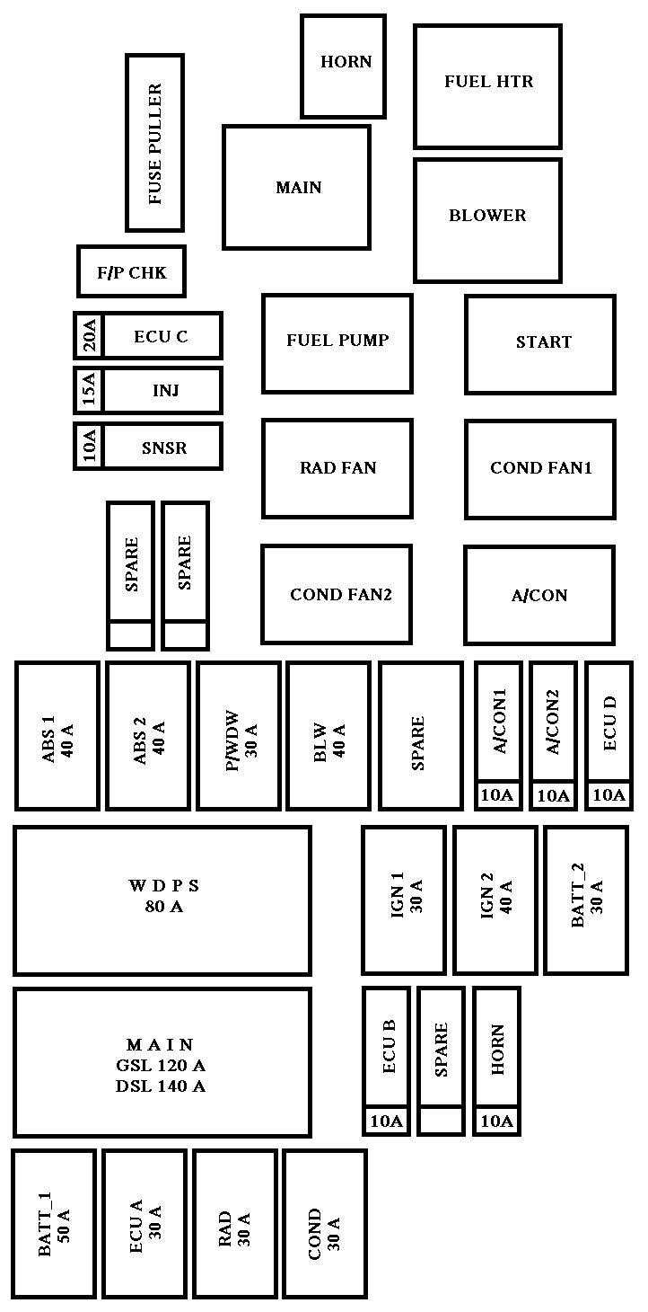
Maxi fuse (engine compartment)
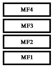
Peugeot 106 DAG - fuse box - engine compartment - maxi fuse
Peugeot 106 – fuse box – engine compartment – maxi fuse
Fuse Ampere rating [A] Functions
MF1 20 Lighting switch
MF2 80 Ignition supply (starter +ve)
MF3 40 Ignition supply (ignition controlled +ve)
MF4 40 Battery +ve feed to 13-fuse box

Passenger compartment

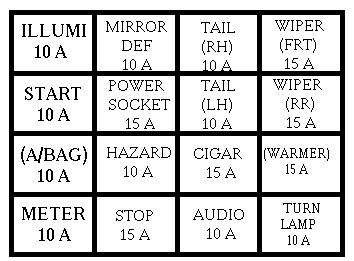
13 fuse box (passenger compartment)

Peugeot 106 DAG - fuse box - passenger compartment
Peugeot 106 – fuse box – passenger compartment
Fuse Ampere rating [A] Functions
1 Not used
2 25 Heater blower
3 25 Heated rear screen – air conditioning – pressure switch – heated seats
4 25 Radio – map reading light
5 30 Heated rear screen – horn – lighter + heated mirrors
6 10 Direction indicators / hazard warning lights
7 10 Engine cooling – electronic immobiliser – coolant temperature control unit – instrument panel – power steering – reversing lights
8 20 Central locking – electronic immobiliser – interior lighting – boot lighting – coolant temperature control unit – instrument panel – radio – clock
9 30 Electric windows – hazard warning lights – electric mirrors – brake lights – front and rear wipers – instrument panel
10 20 Front electric windows
11 5 Rear fog light + instrument panel lights
12 5 Left tail-light – front sidelights – instrument panel lighting (rheostat) + headlamp height adjustment
13 5 Switch lighting – radio panel lighting  – number plate lighting – right tail light

WARNING: Terminal and harness assignments for individual connectors will vary depending on vehicle equipment level, model, and market.

Kia Sephia Sport (2005 – 2009) – fuse box diagram

Kia Sephia Sport mk2 (2005 – 2009) – fuse box diagram

Also called:

  • Kia Rio
  • Kia Pride
  • Kia Rio Xcite

Year of production: 2005, 2006, 2007, 2008, 2009

Engine compartment

Kia Rio mk2 - fuse box - engine compartment
Kia Sephia Sport  – fuse box – engine compartment
Description Fuse rating [A] Protected component
BATT_1 50 Alternator, Battery
ECU A 30 Engine control unit
RAD 30 Radiator fan
COND 30 Condenser fan
ECU B 10 Engine control unit
SPARE Spare fuse
HORN 10 Horn
IGN1 30 Ignition
IGN2 40 Ignition
BATT_2 Alternator, Battery
MAIN 125 Alternator
MDPS 80 Power steering wheel
ABS1 40 ABS
ABS2 40 ABS
P/WDW 30 Power window
BLW 40 Blower
SPARE Spare fuse
A/CON1 10 Air conditioner
A/CON2 10 Air conditioner
ECU D 10 Engine control unit
SNSR 10 Sensor
INJ 15 Injector
ECU C 20 Engine control unit
SPARE Spare fuse
SPARE Spare fuse
HORN Horn relay
MAIN Main relay
FUEL PUMP Fuel pump relay
RAD FAN Radiator fan relay
COND FAN2 Condenser fan relay
FUEL HTR Fuel filter heater relay
BLOWER Blower motor relay
START Start motor relay
COND FAN1 Condenser fan relay
A/CON Air conditioner relay

Driver-side knee bolster

KIA Rio mk2 - fuse box - driver's side knee bloster
KIA Sephia Sport – fuse box – driver’s side knee bloster
Description Fuse rating [A] Protected component
RR WIPER 15 Rear wiper
H/LP (LH) 10 Headlight (left)
FR WIPER 25 Front wiper
BLOWER 10 Blower
H/LP(RH) 10 Headlight (right)
S/ROOF 20 Sunroof
STOP LP 15 Stop light
C/DR LOCK 20 Central door lock
IGN COIL 15 Ignition coil
ABS 10 ABS
B/UP LP 10 Back-up light
SPARE Spare fuse
C/LIGHTER 25 Cigar lighter
FOLD’G 10 Outside rearview mirror folding
HTD SEAT 20 Seat warmer
AMP 25 Amplifier
FR FOG LP 10 Front fog light
SPARE Spare fuse
ECU 10 Engine control unit
CLUSTER 10 Cluster
P/WDW RH 25 Power window (right)
AUDIO 10 Audio
RR FOG LP 10 Rear fog light
IGN 10 Ignition
HTD GLASS 30 Rear window defroster
A/BAG 15 Air bag
TCU 10 Automatic transaxle control
SNSR 10 Sensor
SPARE Spare fuse
MULT B/UP 10 Cluster, ETACS, A/C, Clock, Room lamp
AUDIO 15 Audio
P/WDW LH 25 Power window (left)
HTD MIRR 10 Outside rearview mirror heater
TAIL LP(LH) 10 Taillight (left)
TAIL LP(RH) 10 Taillight (right)
HAZARD 10 Hazard warning light
T/SIG LP 10 Turn signal light
A/BAG IND 10 Air bag warning
START 10 Start motor

WARNING: Terminal and harness assignments for individual connectors will vary depending on vehicle equipment level, model, and market.

Kia Pride mk2 (2005 – 2009) – fuse box diagram

Kia Pride mk2 (2005 – 2009) – fuse box diagram

Also called:

  • Kia Rio
  • Kia Sephia Sport
  • Kia Rio Xcite

Year of production: 2005, 2006, 2007, 2008, 2009

Engine compartment

Kia Rio mk2 - fuse box - engine compartment
Kia Pride mk2 – fuse box – engine compartment
Description Fuse rating [A] Protected component
BATT_1 50 Alternator, Battery
ECU A 30 Engine control unit
RAD 30 Radiator fan
COND 30 Condenser fan
ECU B 10 Engine control unit
SPARE Spare fuse
HORN 10 Horn
IGN1 30 Ignition
IGN2 40 Ignition
BATT_2 Alternator, Battery
MAIN 125 Alternator
MDPS 80 Power steering wheel
ABS1 40 ABS
ABS2 40 ABS
P/WDW 30 Power window
BLW 40 Blower
SPARE Spare fuse
A/CON1 10 Air conditioner
A/CON2 10 Air conditioner
ECU D 10 Engine control unit
SNSR 10 Sensor
INJ 15 Injector
ECU C 20 Engine control unit
SPARE Spare fuse
SPARE Spare fuse
HORN Horn relay
MAIN Main relay
FUEL PUMP Fuel pump relay
RAD FAN Radiator fan relay
COND FAN2 Condenser fan relay
FUEL HTR Fuel filter heater relay
BLOWER Blower motor relay
START Start motor relay
COND FAN1 Condenser fan relay
A/CON Air conditioner relay

Driver-side knee bolster

KIA Rio mk2 - fuse box - driver's side knee bloster
KIA Pride mk2 – fuse box – driver’s side knee bloster
Description Fuse rating [A] Protected component
RR WIPER 15 Rear wiper
H/LP (LH) 10 Headlight (left)
FR WIPER 25 Front wiper
BLOWER 10 Blower
H/LP(RH) 10 Headlight (right)
S/ROOF 20 Sunroof
STOP LP 15 Stop light
C/DR LOCK 20 Central door lock
IGN COIL 15 Ignition coil
ABS 10 ABS
B/UP LP 10 Back-up light
SPARE Spare fuse
C/LIGHTER 25 Cigar lighter
FOLD’G 10 Outside rearview mirror folding
HTD SEAT 20 Seat warmer
AMP 25 Amplifier
FR FOG LP 10 Front fog light
SPARE Spare fuse
ECU 10 Engine control unit
CLUSTER 10 Cluster
P/WDW RH 25 Power window (right)
AUDIO 10 Audio
RR FOG LP 10 Rear fog light
IGN 10 Ignition
HTD GLASS 30 Rear window defroster
A/BAG 15 Air bag
TCU 10 Automatic transaxle control
SNSR 10 Sensor
SPARE Spare fuse
MULT B/UP 10 Cluster, ETACS, A/C, Clock, Room lamp
AUDIO 15 Audio
P/WDW LH 25 Power window (left)
HTD MIRR 10 Outside rearview mirror heater
TAIL LP(LH) 10 Taillight (left)
TAIL LP(RH) 10 Taillight (right)
HAZARD 10 Hazard warning light
T/SIG LP 10 Turn signal light
A/BAG IND 10 Air bag warning
START 10 Start motor

WARNING: Terminal and harness assignments for individual connectors will vary depending on vehicle equipment level, model, and market.

Kia Rio (2006 – 2009) – fuse box diagram

Kia Rio (2006 – 2009) – fuse box diagram

Year of production: 2006, 2007, 2008, 2009

Engine compartment

Kia Rio mk2 - fuse box - engine compartment
Kia Rio mk2 – fuse box – engine compartment
Description Fuse rating [A] Protected component
BATT_1 50 Alternator, Battery
ECU A 30 Engine control unit
RAD 30 Radiator fan
COND 30 Condenser fan
ECU B 10 Engine control unit
SPARE Spare fuse
HORN 10 Horn
IGN1 30 Ignition
IGN2 40 Ignition
BATT_2 Alternator, Battery
MAIN 125 Alternator
MDPS 80 Power steering wheel
ABS1 40 ABS
ABS2 40 ABS
P/WDW 30 Power window
BLW 40 Blower
SPARE Spare fuse
A/CON1 10 Air conditioner
A/CON2 10 Air conditioner
ECU D 10 Engine control unit
SNSR 10 Sensor
INJ 15 Injector
ECU C 20 Engine control unit
SPARE Spare fuse
SPARE Spare fuse
HORN Horn relay
MAIN Main relay
FUEL PUMP Fuel pump relay
RAD FAN Radiator fan relay
COND FAN2 Condenser fan relay
FUEL HTR Fuel filter heater relay
BLOWER Blower motor relay
START Start motor relay
COND FAN1 Condenser fan relay
A/CON Air conditioner relay


Driver-side knee bolster

KIA Rio mk2 - fuse box - driver's side knee bloster
KIA Rio mk2 – fuse box – driver’s side knee bloster
Description Fuse rating [A] Protected component
RR WIPER 15 Rear wiper
H/LP (LH) 10 Headlight (left)
FR WIPER 25 Front wiper
BLOWER 10 Blower
H/LP(RH) 10 Headlight (right)
S/ROOF 20 Sunroof
STOP LP 15 Stop light
C/DR LOCK 20 Central door lock
IGN COIL 15 Ignition coil
ABS 10 ABS
B/UP LP 10 Back-up light
SPARE Spare fuse
C/LIGHTER 25 Cigar lighter
FOLD’G 10 Outside rearview mirror folding
HTD SEAT 20 Seat warmer
AMP 25 Amplifier
FR FOG LP 10 Front fog light
SPARE Spare fuse
ECU 10 Engine control unit
CLUSTER 10 Cluster
P/WDW RH 25 Power window (right)
AUDIO 10 Audio
RR FOG LP 10 Rear fog light
IGN 10 Ignition
HTD GLASS 30 Rear window defroster
A/BAG 15 Air bag
TCU 10 Automatic transaxle control
SNSR 10 Sensor
SPARE Spare fuse
MULT B/UP 10 Cluster, ETACS, A/C, Clock, Room lamp
AUDIO 15 Audio
P/WDW LH 25 Power window (left)
HTD MIRR 10 Outside rearview mirror heater
TAIL LP(LH) 10 Taillight (left)
TAIL LP(RH) 10 Taillight (right)
HAZARD 10 Hazard warning light
T/SIG LP 10 Turn signal light
A/BAG IND 10 Air bag warning
START 10 Start motor

WARNING: Terminal and harness assignments for individual connectors will vary depending on vehicle equipment level, model, and market.

Kia Pride mk1 (2003 – 2005) – fuse box diagram

Kia Pride mk1 (2003 – 2005) – fuse box diagram

Also called:

  • Rio Rio

Year of production: 2003, 2004, 2005

Driver’s side kick panel

KIA Rio mk1 - fuse box - driver's side kick panel
KIA Pride mk1 – fuse box – driver’s side kick panel
Description Fuse rating [A] Protected component
(A/BAG) 10 Airbag
TURN LAMP 10 Turn signal lamp
METER 10 Meterset Backup lamp, Warning sound
ILLUMI 10 Illumination
POWER SOCKET 15 Turn room lamp, Power socket
HAZARD 10 Hazard lamp
STOP 15 Stop lamp, ABS
TAIL (RH) 10 Tail lamp (Right-Rear/Left-Front). Switch illumination
TAIL (LH) 10 Tail lamp (Left-Rear/Right-Front)
CIGAR 15 Cigarette lighter
AUDIO 10 Audio, Electric rearview mirror
WIPER (FRT) 15 Wiper (Rear), Washer (Rear)
(WARMER) 15 Seatwarmer
MIRROR DEF 10 Mirror defroster
START 10 Engine control unit, ECAT unit
(): Optional

Engine compartment

KIA Rio mk1 - fuse box - engine compartment
KIA Pride mk1 – fuse box – engine compartment
Description Fuse rating [A] Protected component
(ABS) 15 ABS
RR FOG 10 Rear fog light (if equipped)
(F/FOG) 15 Front fog light (if equipped)
MAIN 80 Battery is not rechargeable
IG 1 30 (It will be automatically connected to the secondary fuse)

CIGAR – 10 A

AUDIO – 10 A

IG COIL – 15 A

TURN LAMP – 10 A

A/BAG – 10 A

WIPER (RR) – 15 A

WIPER (FRT) – 15 A

RELAY – 10 A

START – 10 A


BLOWER 30 Heater
COOLING 30 Cooling fan
(ABS 1) 30 ABS
COND. FAN 20 Condenser fan
HEAD-HI 15 Head lamp light
HEAD-LOW 15 Head lamp low
EMS 10 Engine sensor
INJECTOR 15 Injector, O2 sensor
F/PUMP 10 Fuel pump
ECU 10 Engine control unit, ECAT unit, Main relay
RELAY 10 Blower motor, Power window, Rear window defroster, Head lamp (Airbag equipped vehicle)
(HLLD) 10
MAIN RELAY 25 (It will be automatically connected to the secondary fuse)

EMS – 10 A

INJECTOR – 15 A

F/PUMP – 10 A

ECU – 10 A

S/ROOF 15 Sunroof
HEAD 25 (It will be automatically connected to the secondary fuse)

HEAD-HI – 15 A

HEAD-LOW – 15 A

FOG LAMP (RR) – 10 A

IG 2 30
TNS 15 (It will be automatically connected to the secondary fuse)

TAIL (LH) – 10 A

TAIL (RH) – 10 A

HORN 10 Horn
RR DEF 25 Rear window defroster
(ABS 2) 20 ABS
P/WIN 30 Power window
BTN 30 (It will be automatically connected to the secondary fuse)

MEMORY/ROOM – 10 A

STOP – 15 A

HAZARD – 15 A

D/LOCK 25 Power door lock
IG COIL 15 Ignition coil
ROOM 15 Room LAMP, Audio, Meterset, Warning sound
(): Optional

WARNING: Terminal and harness assignments for individual connectors will vary depending on vehicle equipment level, model, and market.

Kia Rio (2003 – 2005) – fuse box diagram

Kia Rio (2003 – 2005) – fuse box diagram

Year of production: 2003, 2004, 2005

Driver’s side kick panel

KIA Rio mk1 - fuse box - driver's side kick panel
KIA Rio mk1 – fuse box – driver’s side kick panel
Description Fuse rating [A] Protected component
(A/BAG) 10 Airbag
TURN LAMP 10 Turn signal lamp
METER 10 Meterset Backup lamp, Warning sound
ILLUMI 10 Illumination
POWER SOCKET 15 Turn room lamp, Power socket
HAZARD 10 Hazard lamp
STOP 15 Stop lamp, ABS
TAIL (RH) 10 Tail lamp (Right-Rear/Left-Front). Switch illumination
TAIL (LH) 10 Tail lamp (Left-Rear/Right-Front)
CIGAR 15 Cigarette lighter
AUDIO 10 Audio, Electric rearview mirror
WIPER (FRT) 15 Wiper (Rear), Washer (Rear)
(WARMER) 15 Seatwarmer
MIRROR DEF 10 Mirror defroster
START 10 Engine control unit, ECAT unit
(): Optional

Engine compartment

KIA Rio mk1 - fuse box - engine compartment
KIA Rio mk1 – fuse box – engine compartment
Description Fuse rating [A] Protected component
(ABS) 15 ABS
RR FOG 10 Rear fog light (if equipped)
(F/FOG) 15 Front fog light (if equipped)
MAIN 80 Battery is not rechargeable
IG 1 30 (It will be automatically connected to the secondary fuse)

CIGAR – 10 A

AUDIO – 10 A

IG COIL – 15 A

TURN LAMP – 10 A

A/BAG – 10 A

WIPER (RR) – 15 A

WIPER (FRT) – 15 A

RELAY – 10 A

START – 10 A


BLOWER 30 Heater
COOLING 30 Cooling fan
(ABS 1) 30 ABS
COND. FAN 20 Condenser fan
HEAD-HI 15 Head lamp light
HEAD-LOW 15 Head lamp low
EMS 10 Engine sensor
INJECTOR 15 Injector, O2 sensor
F/PUMP 10 Fuel pump
ECU 10 Engine control unit, ECAT unit, Main relay
RELAY 10 Blower motor, Power window, Rear window defroster, Head lamp (Airbag equipped vehicle)
(HLLD) 10
MAIN RELAY 25 (It will be automatically connected to the secondary fuse)

EMS – 10 A

INJECTOR – 15 A

F/PUMP – 10 A

ECU – 10 A

S/ROOF 15 Sunroof
HEAD 25 (It will be automatically connected to the secondary fuse)

HEAD-HI – 15 A

HEAD-LOW – 15 A

FOG LAMP (RR) – 10 A

IG 2 30
TNS 15 (It will be automatically connected to the secondary fuse)

TAIL (LH) – 10 A

TAIL (RH) – 10 A

HORN 10 Horn
RR DEF 25 Rear window defroster
(ABS 2) 20 ABS
P/WIN 30 Power window
BTN 30 (It will be automatically connected to the secondary fuse)

MEMORY/ROOM – 10 A

STOP – 15 A

HAZARD – 15 A

D/LOCK 25 Power door lock
IG COIL 15 Ignition coil
ROOM 15 Room LAMP, Audio, Meterset, Warning sound
(): Optional

WARNING: Terminal and harness assignments for individual connectors will vary depending on vehicle equipment level, model, and market.

KIA Pride mk1 (1999 – 2002) – fuse box diagram

KIA Pride mk1 (1999 – 2002) – fuse box diagram

Also called:

  • Kia Rio

Year of production: 1999, 2000, 2001, 2002

Driver’s side kick panel

KIA Rio mk1 - fuse box - driver's side kick panel
KIA Pride mk1 – fuse box – driver’s side kick panel
Description Fuse rating [A] Protected component
(A/BAG) 10 Airbag
TURN LAMP 10 Turn signal lamp
METER 10 Meterset, Backup lamp, Warning sound
(FOG LAMP (RR)) 10 Rear Fog lamp
POWER SOCKET 15 Trunk room lamp, power socket
HAZARD 15 Hazard lamp
STOP 15 Stop lamp, ABS
TAIL (RH) 10 Tail lamp (Right-Rear/Left-Front), Switch illumination
TAIL (LH) 10 Tail lamp (Left-Rear/Right-Front)
CIGAR 15 Cigarette lighter
AUDIO 10 Audio, Electric reaview mirror
WIPER (FRT) 15 Wiper (front), Washer (front), Sunroof
(WIPER (RR)) 15 Wiper (Rear), Washer (Rear)
(WARMER) 20 Seatwarmer
(MIRROR DEF) 15 Mirror defroster
START 10 Engine control unit, ECAT unit
(): Optional

Engine compartment

KIA Rio mk1 - fuse box - engine compartment
KIA Pride mk1 – fuse box – engine compartment
Description Fuse rating [A] Protected component
S/B FUSES 1 MAIN 80 Battery is not rechargeable
2 IG KEY1 30 (It will be automatically connected to the secondary fuse)

CIGAR – 10 A

AUDIO – 10 A

IG COIL – 15 A

TURN LAMP – 10 A

A/BAG – 10 A

WIPER (RR) – 15 A

WIPER (FRT) – 15 A

RELAY – 10 A

START – 10 A

3 BLOWER 30 Heater
4 C/FAN 20 Cooling fan
5 (ABS 1) 30 ABS
6
7 (COND. FAN) 20 Condenser fan
MINI FUSES 8 HEAD-HI 15 Head lamp high
9 HEAD-LOW 15 Head lamp low
10 EMS 10 Engine sensors
11 INJECTOR 15 Injector; O2 sensor
12 F/PUMP 10 Fuel pump
13 ECU 10 Engine control unit; ECAT unit, Main relay
14 RELAY 10 Blower motor, Power window, Rear window defroster, Head lamp (Airbag equipped vehicle)
15 MAIN RELAY 25 (It will be automatically connected to the secondary fuse)

EMS – 10 A

INJECTOR – 15 A

F/PUMP – 10 A

ECU – 10 A

16 S/ROOF 15 Sunroof
17 HEAD 25 (It will be automatically connected to the secondary fuse)

HEAD-HI – 15 A

HEAD -LOW – 15 A

FOG LAMP (RR) – 10 A

18
19
20 (HLLD) 10 Headlight Leveling Device (if equipped)
21 IG KEY2 25
22 TNS 15 (It will be automatically connected to the secondary fuse)

TAIL (LH) – 10 A

TAIL (RH) – 10A

23 HORN 10 Horn
24 RR DEF 20 Rear window defroster
25 (ABS 2) 20 ABS
26 (P/WIN) 30 Power window
27 BTN 30 (It will be automatically connected to the secondary fuse)

MEMORY/ROOM – 10 A

STOP – 15 A

HAZARD – 15 A

28 (D/LOCK) 25 Power door lock
29 IG COIL 15 Ignition coil
30 MEMORY/ROOM 15 Room LAMP, Audio, Meterset Warring sound
(): Optional

Relays

Relays Description
MINI RELAYS 31 BLOWER
32 P?WIN
MICRO RELAYS 33 COND FAN
34 TNS
35 MAIN
36 H/LAMP
37 C/FAN
38 HORN
39 F/PUMP
40 RR DEF
41 A/CON
(): Optional

WARNING: Terminal and harness assignments for individual connectors will vary depending on vehicle equipment level, model, and market.

KIA Rio (1999 – 2000) – fuse box diagram

KIA Rio (1999 -2000) – fuse box diagram

Also called: Kia Pride

Year of production: 1999, 2000

Driver’s side kick panel

KIA Rio mk1 - fuse box - driver's side kick panel
KIA Rio mk1 – fuse box – driver’s side kick panel
Description Fuse rating [A] Protected component
(A/BAG) 10 Airbag
TURN LAMP 10 Turn signal lamp
METER 10 Meterset, Backup lamp, Warning sound
(FOG LAMP (RR)) 10 Rear Fog lamp
POWER SOCKET 15 Trunk room lamp, power socket
HAZARD 15 Hazard lamp
STOP 15 Stop lamp, ABS
TAIL (RH) 10 Tail lamp (Right-Rear/Left-Front), Switch illumination
TAIL (LH) 10 Tail lamp (Left-Rear/Right-Front)
CIGAR 15 Cigarette lighter
AUDIO 10 Audio, Electric reaview mirror
WIPER (FRT) 15 Wiper (front), Washer (front), Sunroof
(WIPER (RR)) 15 Wiper (Rear), Washer (Rear)
(WARMER) 20 Seatwarmer
(MIRROR DEF) 15 Mirror defroster
START 10 Engine control unit, ECAT unit
(): Optional


Engine compartment

KIA Rio mk1 - fuse box - engine compartment
KIA Rio mk1 – fuse box – engine compartment
Description Fuse rating [A] Protected component
S/B FUSES 1 MAIN 80 Battery is not rechargeable
2 IG KEY1 30 (It will be automatically connected to the secondary fuse)

CIGAR – 10 A

AUDIO – 10 A

IG COIL – 15 A

TURN LAMP – 10 A

A/BAG – 10 A

WIPER (RR) – 15 A

WIPER (FRT) – 15 A

RELAY – 10 A

START – 10 A

3 BLOWER 30 Heater
4 C/FAN 20 Cooling fan
5 (ABS 1) 30 ABS
6
7 (COND. FAN) 20 Condenser fan
MINI FUSES 8 HEAD-HI 15 Head lamp high
9 HEAD-LOW 15 Head lamp low
10 EMS 10 Engine sensors
11 INJECTOR 15 Injector; O2 sensor
12 F/PUMP 10 Fuel pump
13 ECU 10 Engine control unit; ECAT unit, Main relay
14 RELAY 10 Blower motor, Power window, Rear window defroster, Head lamp (Airbag equipped vehicle)
15 MAIN RELAY 25 (It will be automatically connected to the secondary fuse)

EMS – 10 A

INJECTOR – 15 A

F/PUMP – 10 A

ECU – 10 A

16 S/ROOF 15 Sunroof
17 HEAD 25 (It will be automatically connected to the secondary fuse)

HEAD-HI – 15 A

HEAD -LOW – 15 A

FOG LAMP (RR) – 10 A

18
19
20 (HLLD) 10 Headlight Leveling Device (if equipped)
21 IG KEY2 25
22 TNS 15 (It will be automatically connected to the secondary fuse)

TAIL (LH) – 10 A

TAIL (RH) – 10A

23 HORN 10 Horn
24 RR DEF 20 Rear window defroster
25 (ABS 2) 20 ABS
26 (P/WIN) 30 Power window
27 BTN 30 (It will be automatically connected to the secondary fuse)

MEMORY/ROOM – 10 A

STOP – 15 A

HAZARD – 15 A

28 (D/LOCK) 25 Power door lock
29 IG COIL 15 Ignition coil
30 MEMORY/ROOM 15 Room LAMP, Audio, Meterset Warring sound
(): Optional


Relays

Relays Description
MINI RELAYS 31 BLOWER
32 P?WIN
MICRO RELAYS 33 COND FAN
34 TNS
35 MAIN
36 H/LAMP
37 C/FAN
38 HORN
39 F/PUMP
40 RR DEF
41 A/CON
(): Optional

WARNING: Terminal and harness assignments for individual connectors will vary depending on vehicle equipment level, model, and market.

KIA K5 Hybryd (2011 – 2015) – fuse box diagram

KIA K5 Hybryd (2011 – 2015) – fuse box diagram

Also called:

  • Kia Optima
  • Kia Optima K5 (Malaysia)

Inner fuse panel (Driver’s side fuse panel)Year of production: 2011, 2012, 2013, 2014, 2015

Description Fuse rating [A] Protected component
MODULE 3 7,5 Sport Mode Switch, Natural Vacuum Leak Detection, VESS Unit
PDM 1 25 Smart Key Control Module
POWER OUTLET 15 Front Power Outlet
MODULE 5 7,5 Smart Key Control Module, Rear Seat Warmer Relay LH/RH
MODULE 2 7,5 BCM, Panorama Sunroof, Rain Sensor
TRUNK 10 I/P Junction Box (Trunk Lid Relay), Fuel Filler Door & Trunk Lid Switch, Trunk Room Lamp
CLOCK 10 A/V & Navigation Head Unit, Audio, Smart Key Control Module, Overhead Console Lamp, Crash Pad Mood Lamp, VESS Unit,A/C Control Module, BCM, AMP, Power Outside Mirror Switch, Driver/Passenger Door Mood Lamp
C/LIGHTER 15 Cigarette Lighter
HTD STRG 15 Steering Wheel Heater
A/CON 7,5 A/C Control Module, E/R Fuse & Relay Box (Blower Relay, Water Pump Relay), Electronic A/C Compressor
WIPER 25 Multifunction Switch, Front Wiper Motor, E/R Fuse & Relay Box (Wiper Relay, Rain SNSR Relay)
S/HEATER FRT 20 Driver/Passenger CCS Cushion Warmer, Driver/Passenger Seat Warmer Module
E_WATER_PUMP 10 Hybrid Water Pump
HTD MIRR 10 Driver/Passenger Power Outside Mirror
MODULE 4 HEV 7,5 MCU, Hydraulic Power Unit, Low Voltage DC-DC Converter, BMS Control Module,
Active Air Flap
MCU, Hydraulic Power Unit, Low Voltage DC-DC Converter, BMS Control Module,
Active Air Flap
7,5 Instrument Cluster (Air Bag IND.)
START 7,5 Transaxle Range Switch, Hybrid Control Unit
S/HEATER RR 15 Rear Seat Warmer Relay LH/RH
P/SEAT PASS 20 Passenger Seat Manual Switch
MODULE 1 7,5 Head Lamp Leveling Device Actuator LH/RH, Auto Head Lamp Leveling Device Module, Driver IMS Module, BCM, Front Seat Warmer & CCS Switch, Driver/Passenger CCS Control Module, Driver/Passenger Seat Warmer Module, Audio, A/C Control Module, Electro Chromic Mirror, Lane Keeping Assist Module, Instrument Cluster
HCU 20 Hybrid Control Unit
A/BAG 15 Telltale Lamp, SRS Control Module, Passenger Weight Classification Sensor
P/WDW LH 25 I/P Junction Box (Power Window LH Relay), Driver Safety Power Window Module
AMP 30 AMP
PDM 2 7,5 Start Stop Button Switch, Smart Key Control Module, Fob Holder, Stop Lamp Switch
BMS 10 BMS Control Module
MDPS 10 EPS Control Module, Crash Pad Switch, Tire Pressure Monitoring Module, ATM Lever Indicator
PDM 3 7,5 Smart Key Control Module
P/WDW RH 25 I/P Junction Box (Power Window RH Relay), Passenger Safety Power Window Module
P/SEAT DRV 30 Driver IMS Module, Driver Seat Manual Switch, Driver Lumbar Support Switch
DR LOCK 20 Two Turn Unlock Relay, I/P Junction Box (Door Lock Relay, Door Unlock Relay, Turn Signal Lamp Sound Relay)
SUNROOF 20 Panorama Sunroof
IG 1 20 E/R Fuse & Relay Box (Fuse : ESC 3 10A, TCU 2 15A, ECU 4 10A, OPCU 2 10A)
POWER CONNECTOR – AUDIO 15 A/V & Navigation Head Unit, Audio
POWER CONNECTOR – ROOM LP 10 Driver/Passenger Smart Key Outside Handle, Driver IMS Module, Lamp Auto Cut Relay, Driver/Passenger Door Scuff Lamp, A/C Control Module, Data Link Connector, RF Receiver, BCM, Electro Chromic Mirror, Instrument Cluster, Auto Light & Photo Sensor, Tire Pressure Monitoring Module

Engine compartment main fuse panel

Description Fuse rating [A] Protected component
MULTI FUSE IP B+ 2 60 I/P Junction Box (P/SEAT DRV 30A, P/SEAT PASS 20A, AMP 30A, PDM 2 7.5A, IPS 5, IPS 6, ARISU 2)
AHB 1 60 Hydraulic Power Unit
IGN 2 40 E/R Fuse & Relay Box (PDM 3 (IG 2) Relay)
ESC 1 40 ESC Module
RR HTD 40 E/R Fuse & Relay Box (RR HTD Relay)
BLOWER 40 E/R Fuse & Relay Box (Blower Relay)
IP B+ 1 60 I/P Junction Box (PDM 1 25A, MODULE 3 7.5A, S/HEATER FRT 20A, S/HEATER RR 15A, TRUNK 10A, P/WDW LH 25A, P/WDW RH 25A), Power Connector (AUDIO 15A))
MDPS 80 EPS Control Module
FUSE WIPER 10 PCM
RR HTD IND 10 A/C Control Module
OPCU 1 20 Electric Oil Pump Unit
INVERTER 10 MCU, Low Voltage DC-DC Converter, Active Air Flap
TCU 1 20 PCM
STOP LP 15 Hybrid Fuse & Relay Box (HAC Relay), Smart Key Control Module, Stop Lamp Relay
DEICER 20 E/R Fuse & Relay Box (Deicer Relay)
WATER PUMP 10 E/R Fuse & Relay Box (Water Pump Relay)
BMS C/FAN 20 BMS Blower Motor Relay
IP B+ 3 50 I/P Junction Box (Power Connector (ROOM LP 10A), SUNROOF 20A, DR LOCK 20A, BMS 10A, IPS 1, IPS 3, ARISU 1)
ESC 2 30 Multipurpose Check Connector, ESC Module
HCU 20 Hybrid Control Unit
AHB 2 30 Hydraulic Power Unit
C/FAN (LO) 40 E/R Fuse & Relay Box (C/Fan(LO) Relay)
IGN 1 40 E/R Fuse & Relay Box (PDM 1(ACC) Relay, PDM 2(IG 1) Relay)
EMS 40 EMS Box (HORN 15A, ECU 3 10A, ECU 1 30A, F/PUMP 20A)
ECU 4 10 PCM
TCU 2 15 Transaxle Range Switch
ESC 3 10 Hybrid Fuse & Relay Box (HAC Relay), Stop Lamp Switch, ESC Module, Multipurpose Check Connector
B/UP LP 10 A/V & Navigation Head Unit, Audio, Electro Chromic Mirror, BCM, Rear Combination Lamp(IN) LH/RH
OPCU 2 10 Hybrid Fuse & Relay Box (OPCU Relay), Electric Oil Pump Unit

Engine compartment main fuse panel (Engine junction fuses)

Relay no. Relay name Type
E41 RR HTD Relay PLUG MICRO
E42 PDM 1 (ACC) Relay PLUG MICRO
E43 Water Pump Relay PLUG MICRO
E44 C/FAN (LO) Relay PLUG MICRO
E47 Deicer Relay PLUG MICRO
E49 PDM 2 (IG1) Relay PLUG MICRO
E50 PDM 3 (IG2) Relay PLUG MICRO
E51 Wiper Relay PLUG MICRO
E52 Rain SNSR Relay PLUG MICRO
E53 B/Horn Relay PLUG MICRO
E54 Blower Relay PLUG MICRO

Engine compartment sub fuse panel (Sub-relay box)

Description Fuse rating Protected component
OPCU 80 OPCU Relay
C/FAN 60 C/FAN HI Relay

WARNING: Terminal and harness assignments for individual connectors will vary depending on vehicle equipment level, model, and market.

KIA Optima Hybryd (2011 – 2013) – fuse box diagram

KIA Optima Hybryd (2011 – 2013) – fuse box diagram

Year of production: 2011, 2012, 2013

Inner fuse panel (Driver’s side fuse panel)

Description Fuse rating [A] Protected component
MODULE 3 7,5 Sport Mode Switch, Natural Vacuum Leak Detection, VESS Unit
PDM 1 25 Smart Key Control Module
POWER OUTLET 15 Front Power Outlet
MODULE 5 7,5 Smart Key Control Module, Rear Seat Warmer Relay LH/RH
MODULE 2 7,5 BCM, Panorama Sunroof, Rain Sensor
TRUNK 10 I/P Junction Box (Trunk Lid Relay), Fuel Filler Door & Trunk Lid Switch, Trunk Room Lamp
CLOCK 10 A/V & Navigation Head Unit, Audio, Smart Key Control Module, Overhead Console Lamp, Crash Pad Mood Lamp, VESS Unit,A/C Control Module, BCM, AMP, Power Outside Mirror Switch, Driver/Passenger Door Mood Lamp
C/LIGHTER 15 Cigarette Lighter
HTD STRG 15 Steering Wheel Heater
A/CON 7,5 A/C Control Module, E/R Fuse & Relay Box (Blower Relay, Water Pump Relay), Electronic A/C Compressor
WIPER 25 Multifunction Switch, Front Wiper Motor, E/R Fuse & Relay Box (Wiper Relay, Rain SNSR Relay)
S/HEATER FRT 20 Driver/Passenger CCS Cushion Warmer, Driver/Passenger Seat Warmer Module
E_WATER_PUMP 10 Hybrid Water Pump
HTD MIRR 10 Driver/Passenger Power Outside Mirror
MODULE 4 HEV 7,5 MCU, Hydraulic Power Unit, Low Voltage DC-DC Converter, BMS Control Module,
Active Air Flap
A/BAG IND 7,5 Instrument Cluster (Air Bag IND.)
START 7,5 Transaxle Range Switch, Hybrid Control Unit
S/HEATER RR 15 Rear Seat Warmer Relay LH/RH
P/SEAT PASS 20 Passenger Seat Manual Switch
MODULE 1 7,5 Head Lamp Leveling Device Actuator LH/RH, Auto Head Lamp Leveling Device Module, Driver IMS Module, BCM, Front Seat Warmer & CCS Switch, Driver/Passenger CCS Control Module, Driver/Passenger Seat Warmer Module, Audio, A/C Control Module, Electro Chromic Mirror, Lane Keeping Assist Module, Instrument Cluster
HCU 20 Hybrid Control Unit
A/BAG 15 Telltale Lamp, SRS Control Module, Passenger Weight Classification Sensor
P/WDW LH 25 I/P Junction Box (Power Window LH Relay), Driver Safety Power Window Module
AMP 30 AMP
PDM 2 7,5 Start Stop Button Switch, Smart Key Control Module, Fob Holder, Stop Lamp Switch
BMS 10 BMS Control Module
MDPS 10 EPS Control Module, Crash Pad Switch, Tire Pressure Monitoring Module, ATM Lever Indicator
PDM 3 7,5 Smart Key Control Module
P/WDW RH 25 I/P Junction Box (Power Window RH Relay), Passenger Safety Power Window Module
P/SEAT DRV 30 Driver IMS Module, Driver Seat Manual Switch, Driver Lumbar Support Switch
DR LOCK 20 Two Turn Unlock Relay, I/P Junction Box (Door Lock Relay, Door Unlock Relay, Turn Signal Lamp Sound Relay)
SUNROOF 20 Panorama Sunroof
IG 1 20 E/R Fuse & Relay Box (Fuse : ESC 3 10A, TCU 2 15A, ECU 4 10A, OPCU 2 10A)
POWER CONNECTOR – AUDIO 15 A/V & Navigation Head Unit, Audio
POWER CONNECTOR – ROOM LP 10 Driver/Passenger Smart Key Outside Handle, Driver IMS Module, Lamp Auto Cut Relay, Driver/Passenger Door Scuff Lamp, A/C Control Module, Data Link Connector, RF Receiver, BCM, Electro Chromic Mirror, Instrument Cluster, Auto Light & Photo Sensor, Tire Pressure Monitoring Module


Engine compartment main fuse panel

Description Fuse rating [A] Protected component
MULTI FUSE IP B+ 2 60 I/P Junction Box (P/SEAT DRV 30A, P/SEAT PASS 20A, AMP 30A, PDM 2 7.5A, IPS 5, IPS 6, ARISU 2)
AHB 1 60 Hydraulic Power Unit
IGN 2 40 E/R Fuse & Relay Box (PDM 3 (IG 2) Relay)
ESC 1 40 ESC Module
RR HTD 40 E/R Fuse & Relay Box (RR HTD Relay)
BLOWER 40 E/R Fuse & Relay Box (Blower Relay)
IP B+ 1 60 I/P Junction Box (PDM 1 25A, MODULE 3 7.5A, S/HEATER FRT 20A, S/HEATER RR 15A, TRUNK 10A, P/WDW LH 25A, P/WDW RH 25A), Power Connector (AUDIO 15A))
MDPS 80 EPS Control Module
FUSE WIPER 10 PCM
RR HTD IND 10 A/C Control Module
OPCU 1 20 Electric Oil Pump Unit
INVERTER 10 MCU, Low Voltage DC-DC Converter, Active Air Flap
TCU 1 20 PCM
STOP LP 15 Hybrid Fuse & Relay Box (HAC Relay), Smart Key Control Module, Stop Lamp Relay
DEICER 20 E/R Fuse & Relay Box (Deicer Relay)
WATER PUMP 10 E/R Fuse & Relay Box (Water Pump Relay)
BMS C/FAN 20 BMS Blower Motor Relay
IP B+ 3 50 I/P Junction Box (Power Connector (ROOM LP 10A), SUNROOF 20A, DR LOCK 20A, BMS 10A, IPS 1, IPS 3, ARISU 1)
ESC 2 30 Multipurpose Check Connector, ESC Module
HCU 20 Hybrid Control Unit
AHB 2 30 Hydraulic Power Unit
C/FAN (LO) 40 E/R Fuse & Relay Box (C/Fan(LO) Relay)
IGN 1 40 E/R Fuse & Relay Box (PDM 1(ACC) Relay, PDM 2(IG 1) Relay)
EMS 40 EMS Box (HORN 15A, ECU 3 10A, ECU 1 30A, F/PUMP 20A)
ECU 4 10 PCM
TCU 2 15 Transaxle Range Switch
ESC 3 10 Hybrid Fuse & Relay Box (HAC Relay), Stop Lamp Switch, ESC Module, Multipurpose Check Connector
B/UP LP 10 A/V & Navigation Head Unit, Audio, Electro Chromic Mirror, BCM, Rear Combination Lamp(IN) LH/RH
OPCU 2 10 Hybrid Fuse & Relay Box (OPCU Relay), Electric Oil Pump Unit


Engine compartment main fuse panel (Engine junction fuses)

Relay no. Relay name Type
E41 RR HTD Relay PLUG MICRO
E42 PDM 1 (ACC) Relay PLUG MICRO
E43 Water Pump Relay PLUG MICRO
E44 C/FAN (LO) Relay PLUG MICRO
E47 Deicer Relay PLUG MICRO
E49 PDM 2 (IG1) Relay PLUG MICRO
E50 PDM 3 (IG2) Relay PLUG MICRO
E51 Wiper Relay PLUG MICRO
E52 Rain SNSR Relay PLUG MICRO
E53 B/Horn Relay PLUG MICRO
E54 Blower Relay PLUG MICRO

Engine compartment sub fuse panel (Sub-relay box)

Description Fuse rating Protected component
OPCU 80 OPCU Relay
C/FAN 60 C/FAN HI Relay

WARNING: Terminal and harness assignments for individual connectors will vary depending on vehicle equipment level, model, and market.