Kia Optima Hybrid (2014 – 2016) – fuse box diagram
Year of production: 2014, 2015, 2016
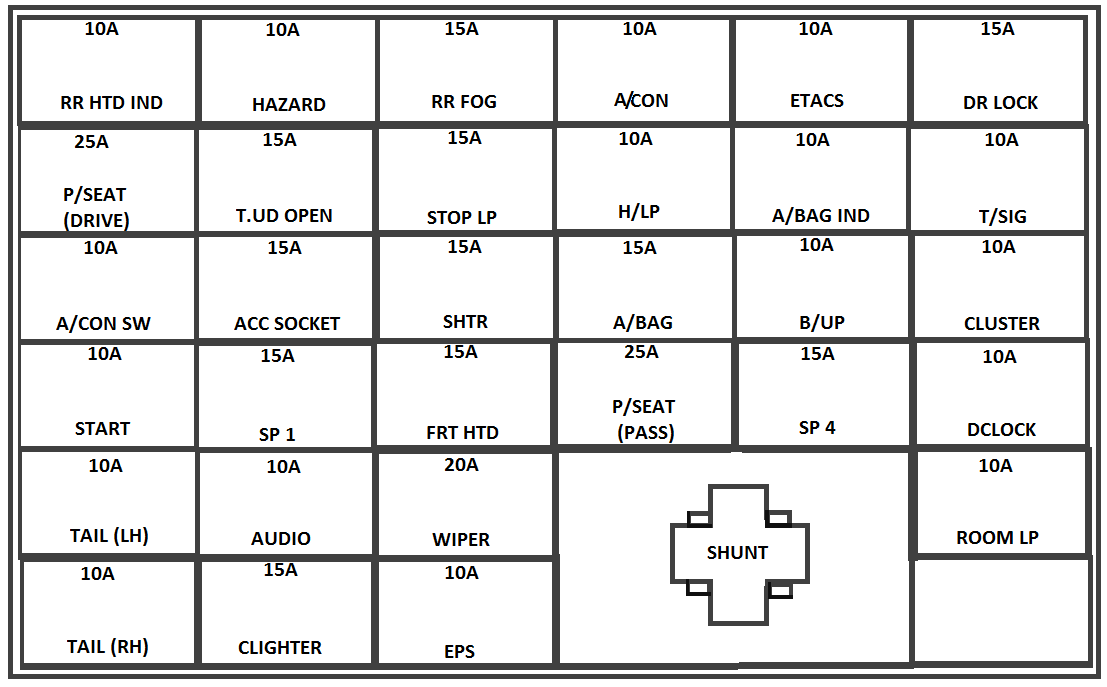
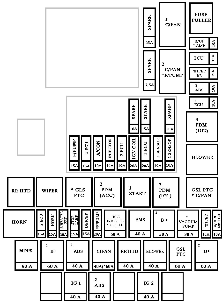
Instrument fuse panel
| Description | Fuse rating [A] | Protected component |
| MULTIMEDIA | 15 | AUDIO_UVO, AUDIO (PA30A,B), NAVI_3.0, NAVI_4.0, TMU |
| PDM 1 | 25 | Smart Key Control Module (With Smart Key) |
| SPARE | 10 | — |
| PDM 2 | 10 | SMK UNIT, BUTTON START SW |
| P/SEAT (PASS) | 20 | Passenger Seat Manual Switch |
| AMP | 30 | AMP |
| P/SEAT(DRV) | 30 | Driver IMS Module, Driver Seat Manual Switch, Driver Lumbar Support Switch (2WAY) |
| MEMORY 2 | 7,5 | PIC_RF_RECEIVER |
| TRUNK | 10 | Trunk Lid Relay, Trunk Room Lamp |
| MODULE 7 | 10 | SPORT_MODE_SW, RR POWER WINDOW SW |
| DR LOCK | 20 | Door Lock/Unlock Relay, Turn Signal Lamp Sound Relay |
| S/HEATER(RR) | 20 | Rear Seat Warmer Relay LH/RH |
| P/WDW(RH) | 25 | Passenger Safety Power Window Module (LHD), Rear Safety Power Window Module RH, Power Window RH Relay |
| P/WDW(LH) | 25 | Driver Safety Power Window Module (LHD), Rear Safety Power, Window Module LH, Power Window LH Relay |
| MODULE 2 | 10 | BCM, Panorama Sunroof, Rain Sensor |
| BRAKE SWITCH | 10 | Smart Key Control Module, Start Stop Button Switch, Stop Lamp Switch |
| MEMORY 1 | 10 | SEAT EXTN (IMS), DR_TRIM_EXTN (FOLD’G), CLUSTER, A/CON, ECM, AUTO FOLDING RLY, TPMS, POWER OUTLET, A_L_PHOTO_SNSR, MUT |
| SUNROOF | 20 | Panorama Sunroof |
| S/HEATER(FRT) SEAT VERNT(FRT) | 20 | SEAT_EXTN (HEAT/VENT) |
| SPARE | 10 | — |
| A/BAG IND | 10 | Instrument Cluster |
| MODULE 3 | 10 | Sport Mode Switch |
| MODULE 4 | 10 | Driver/Passenger CCS Control Module (With CCS), Driver/Passenger Seat Warmer Module (W/O CCS), Front Seat Warmer & CCS Switch, Oil Pump Inverter, Tire Pressure Monitoring Module |
| A/BAG | 15 | A/BAG UNIT IG1 , WCS_PASS IG1 |
| INTERIOR LAMP | 10 | Driver/Passenger Smart Key Outside Handle (With Smart Key), Driver/Passenger Door Lamp, A/C Control Module, RF Receiver (With Smart Key), Driver IMS Module, BCM, Data Link Connector, Driver/Passenger Door Scuff Lamp, Power Outside Mirror Switch, Lamp Auto Cut Relay, Instrument Cluster |
| CLUSTER | 10 | CLUSTER (IGN1) |
| MDPS | 7,5 | Crash Pad Switch, EPS Control Module (With MDPS), ATM Lever Indicator, EPB Switch, EPB Control Module |
| PDM 3 | 7,5 | Smart Key Control Module (With Smart Key) |
| EPB | 10 | EPB |
| HEV ECU | 20 | HCU UNIT IG1 |
| IG 1 | 25 | E/R BOX IG1 |
| BMS | 10 | BMS UNIT B+ |
| POWER OUTLET | 20 | Front Power Outlet |
| MODULE 1 | 10 | Auto Head Lamp Leveling Device Module (Auto HLLD), Head Lamp Leveling Device Switch (Manual HLLD), Head Lamp Leveling Device Actuator LH/RH, BCM, Front Smart Parking Assist Sensor Module, Instrument Cluster, Electro Chromic Mirror, A/C Control Module, Driver IMS Module, Rear Parking Assist Buzzer, Lane Keeping Assist Module |
| START | 7,5 | B/ALARM RLY |
| HTD STRG | 15 | Steering Wheel Heater |
| MODULE 5 | 7,5 | Smart Key Control Module (With Smart Key), Rear Seat, Warmer Relay LH/RH, E/R Fuse & Relay Box (RLY.2), Diesel Box (Fuel Filter Relay) |
| A/CON | 7,5 | A/C Control Module, E/R Fuse & Relay Box (RLY.14) |
| SPARE | 15 | — |
| WIPER | 25 | E/R BOX WIPER RLY |
| C/LIGHTER | 20 | Cigarette Lighter |
| MODULE 6 | 7,5 | PANORAMA SUNROOF (IG2), IONIZER, DSL_BOX, RR_SEAT_WARMER |
| HTD MIRR | 10 | Driver/Passenger Power Outside Mirror |
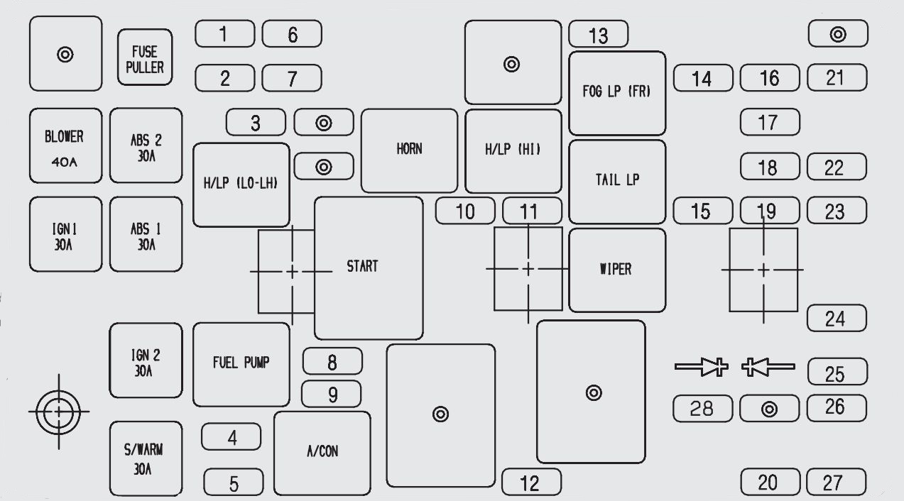
Engine compartment fuse panel
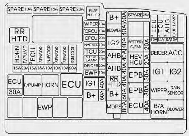
| Description | Fuse rating [A] | Protected component |
| RR HTD | 40 | E/R BOX RR HTD RLY COIL |
| HORN | 15 | HORN (LH, RH) |
| F/PUMP | 20 | FUEL PUMP MTR |
| ECU3 | 15 | PCU (GDI) BATT. DIRECT |
| SENSOR 1 | 15 | DN O2 SENSOR (GDI), UP O2 SENSOR (GDI) |
| INJECTOR | 10 | E/R BOX F/PUMP RLY COIL |
| SENSOR 3 | 10 | CMP1, 2 (GDI, TGDI), SMATRA IMMOBILIZER |
| SENSOR 2 | 10 | CKP (GDI), VIS (GDI), OCV1, 2 (GDI), PCSV (GDI), CCV (GDI) |
| IGN COIL | 20 | ENGINE IG COIL |
| ECU 1 | 30 | ECU RLY |
| SPARE | 10 | — |
| SPARE | 15 | — |
| SPARE | 20 | — |
| WIPER | 10 | BCM, RAIN SNSR, WIPER MTR |
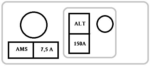
| AMS | 10 | BATTERY SENSOR |
| OPCU 1 | 20 | OPCU UNIT B+ |
| OPCU 2 | 20 | OPCU UNIT IG1 |
| TCU 1 | 20 | TCU |
| STOP LAMP | 15 | RLY.10 (HAC Relay), STOP LAMP RELAY |
| DEICER | 20 | RLY.7 (Deicer Relay) |
| IG1 | 40 | IGN SW |
| B+ 1 | 50 | B+ |
| B+ 2 | 60 | B+ |
| BLOWER | 40 | RLY.14 (Blower Relay) |
| IG 2 | 40 | IGN SW, IG2 RLY |
| AHB 1 | 40 | ESC UNIT MOTOR B+, DIAGNOSIS ABS A/B VALVE B+ |
| AHB 2 | 40 | ESC UNIT SOLENOID B+ |
| RR HTD | 40 | RLY.1 (RR HTD Relay) |
| B+ 3 | 60 | B+ |
| MDPS | 80 | EPS Control Module |
| HEV HCU | 20 | TCU UNIT B+ |
| BATTERY C/FAN | 20 | BMS |
| INVERTER | 50 | O_P_INVERTER |
| EPB 2 | 30 | EPB UNIT BATT2 |
| EPB 1 | EPB UNIT BATT1 | |
| ECU 2 | 40 | EMS BOX (B+) |
| ECU 4 | 10 | ENGINE ECU |
| TCU 2 | 15 | SPEED SNSR, POSITION SW, O_P_INVERTER |
| AHB 30 | 10 | ESC UNIT IGN1 |
| B/UP LAMP | 10 | ELECTRO CHROMIC MIRROR, BCM, REAR COMBINATION LAMP (IN) LH/RH |
| EWP | 10 | WATER PUMP MTR B+ |
WARNING: Terminal and harness assignments for individual connectors will vary depending on vehicle equipment level, model, and market.