KIA Forte K3 – from 2011 – fuse box diagram
Also called:
- Kia Cerato
- Kia Forte K3 (KDM)
- Kia Forte K3 (Clombia & Singapore)
- Kia K3 (Forte) or Shuma (Koup) China
- Naza Forte
- Kia Forte Koup
Year of production: 2011, 2012, 2013, 2014, 2015, 2016
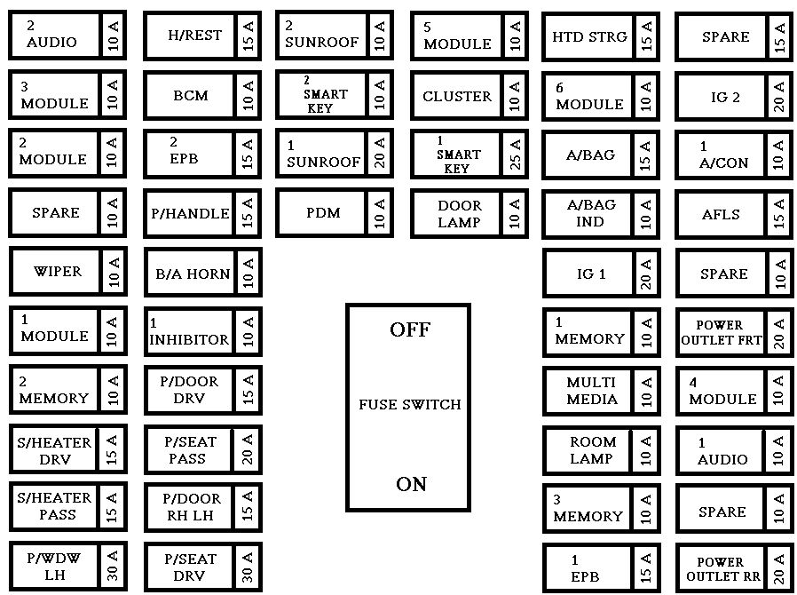
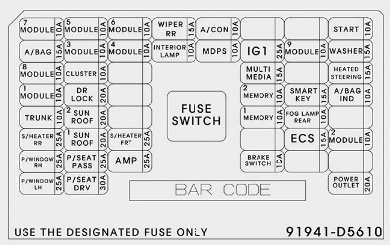
Instrument panel fuse panel
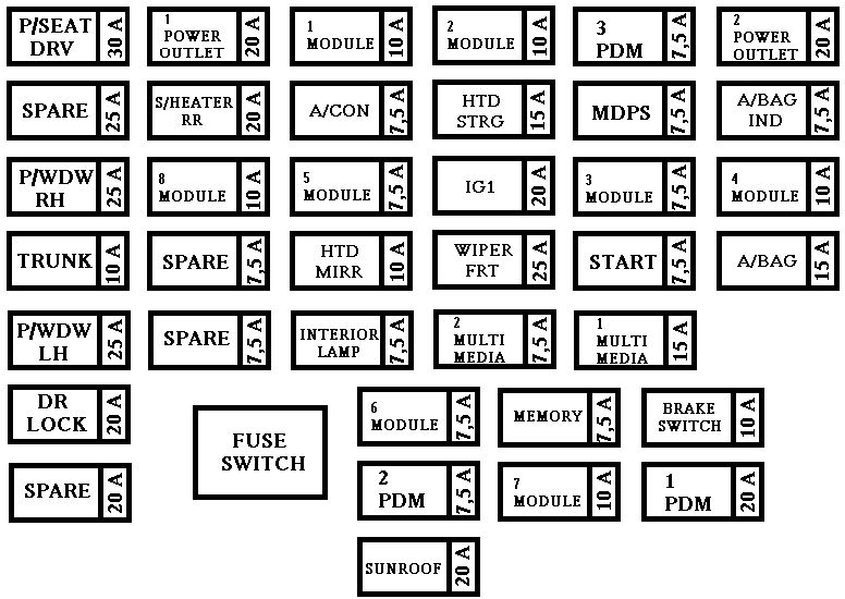
| Fuse name | Fuse rating [A] | Circuit protected |
| P/SEAT DRV | 30 | Driver IMS Module, Driver Seat Manual Switch |
| SPARE 4 | 25 | — |
| P/WDW RH | 25 | Smart Junction Box (Power Window RH Relay), Passenger Safety Power Window Module |
| TRUNK | 10 | Smart Junction Box (Trunk Relay) |
| P/WDW LH | 25 | Smart Junction Box (Power Window LH Relay), Driver Safety Power Window Module |
| DR LOCK | 20 | Smart Junction Box (Door Lock Relay, Door Unlock Relay), ICM Relay Box (Two Turn Unlock Relay) |
| SPARE 3 | 20 | — |
| POWER OUTLET 1 | 20 | Power Outlet |
| S/HEATER RR | 20 | Rear Seat Warmer LH/RH |
| MODULE 8 | 10 | BCM, Smart Key Control Module |
| SPARE 2 | 7,5 | — |
| SPARE 1 | 15 | — |
| MODULE 1 | 10 | Smart Key Control Module, BCM, Digital Clock, Audio, A/V & Navigation Head Unit, Power Outside Mirror Switch, DC-DC Converter, MTS Module |
| A/CON | 7,5 | A/C Control Module, Cluster Ionizer, E/R Fuse & Relay Box (Blower Relay, GSL PTC Relay) |
| MODULE 5 | 7,5 | Sunroof, Driver CCS Control Module, Passenger Seat Warmer Module, Rear Seat Warmer LH/RH |
| HTD MIRR | 10 | ECM/PCM, A/C Control Module, Driver/Passenger Power Outside Mirror |
| INTERIOR LAMP | 7,5 | Trunk Room Lamp, Glove Box Lamp, Vanity Lamp LH/RH, Room Lamp, Overhead Console Lamp, Ignition Key ILL. & Door Warning Switch (W/O Smart Key) |
| MODULE 6 | 7,5 | Sport Mode Switch, Key Solenoid |
| PDM 2 | 7,5 | [With Smart Key] Smart Key Control Module [W/O Smart Key] Immobilizer Module |
| SUNROOF | 20 | Sunroof |
| MODULE 2 | 10 | Electro Chromic Mirror, Multipurpose Check Connector, A/C Control Module, Driver CCS Switch, Driver CCS Control Module, Passenger Seat Warmer Module Driver IMS Module, Passenger Seat Warmer Switch, A/V & Navigation Head Unit, DC-DC Converter, MTS Module, ATM Lever Indicator, PAS Off Switch Rear Seat Warmer LH/RH, Rear Power Window Switch LH/RH |
| HTD STRG | 15 | Steering Wheel Heater |
| IG 1 | 20 | W/O Smart Key : E/R Fuse & Relay Box (Fuse – TCU, ECU 3, ABS 3) |
| WIPER FRT | 25 | Wiper Motor, E/R Fuse & Relay Box (Wiper Relay), Multifunction Switch (Wiper) |
| MULTIMEDIA 2 | 7,5 | Telematics Unit |
| MEMORY | 7,5 | Driver IMS Module, Driver Smart Key Outside Handle, Passenger Smart Key Outside Handle, BCM, Tire Pressure Monitoring Module, Auto Light & Photo Sensor Instrument Cluster, Data Link Connector, Multipurpose Check Connector, Digital Clock, A/C Control Module, Electro Chromic Mirror, Driver Power Outside Mirror Passenger Power Outside Mirror |
| MODULE 7 | 10 | ICM Relay Box (Turn Signal Lamp Sound Relay, Folding Relay, Unfolding Relay) |
| PDM 3 | 7,5 | [With Smart Key] Smart Key Control Module [W/O Smart Key] Immobilizer Module |
| MDPS | 7,5 | MDPS Unit |
| MODULE 3 | 7,5 | Instrument Cluster |
| START | 7,5 | [With Burglar Alarm & W/O Smart Key & W/O IMMO.] ICM Relay Box (Burglar Alarm Relay) [W/O Burglar Alarm or With Smart Key or With IMMO.] Transaxle Range Switch (A/T), E/R Fuse & Relay Box (Start 1 Relay), Smart Key Control Module, ECM |
| MULTIMEDIA 1 | 15 | Audio, A/V & Navigation Head Unit, DC-DC Converter |
| BRAKE SWITCH | 10 | Stop Lamp Switch, Smart Key Control Module |
| PDM 1 | 20 | Smart Key Control Module |
| POWER OUTLET 2 | 20 | Power Outlet |
| A/BAG ING | 7,5 | Instrument Cluster (Air Bag IND.) |
| MODULE 4 | 10 | Crash Pad Switch, Tire Pressure Monitoring Module, Stop Lamp Switch, Digital Clock, BCM, ISG Off Switch, Rear Parking Assist Sensor LH (Out/In) Rear Parking Assist Sensor RH (Out/In), Front Parking Assist Sensor LH/RH |
| A/BAG | 15 | SRS Control Module, Passenger Weight Classification Sensor |
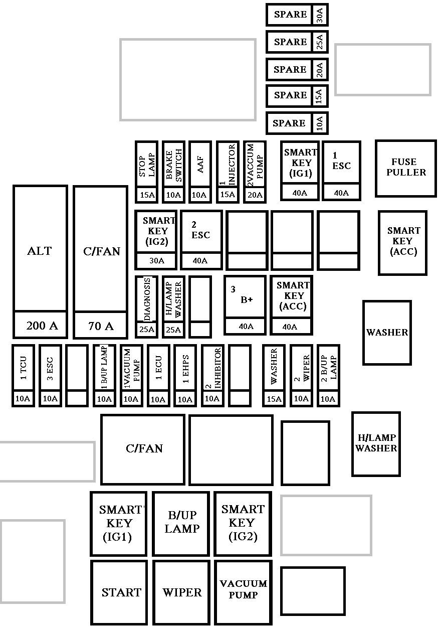
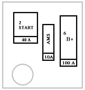
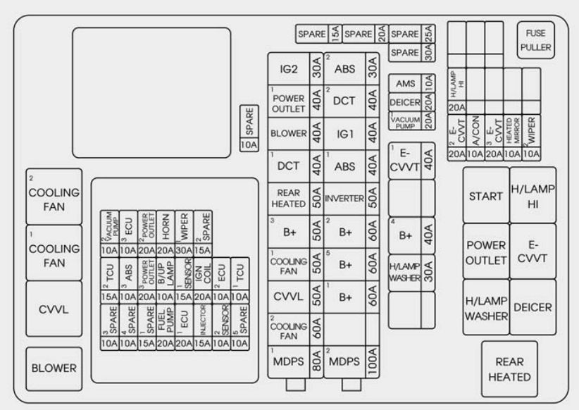
Engine compartment fuse panel
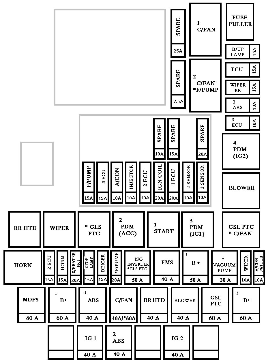
| Description | Fuse name | Fuse rating [A] | Circuit protected |
| MULTI FUSE | MDPS | 80 | MDPS Unit |
| B+1 | 60 | Smart Junction Box (ARISU-LT IPS 1 (4CH), Fuse – MODULE 6, MODULE 7, P/WDW LH, P/WDW RH, TRUNK) | |
| ABS 1 | 40 | ESC Module | |
| C/FAN | 40 | C/Fan 1 Relay, C/Fan 2 Relay | |
| RR HTD | 40 | RR HTD Relay | |
| BLOWER | 40 | Blower Relay | |
| GSL PTC | 60 | GSL PTC Relay | |
| B+2 | 60 | Smart Junction Box (ARISU-LT IPS 3 (4CH), ARISU-LT IPS 4 (4CH), IPS 5 (2CH), Fuse – PDM 1, P/SEAT DRV BRAKE SWITCH, S/HEATER RR) | |
| FUSE | B/UP LAMP | 10 | A/T : Electro Chromic Mirror, Audio, A/V & Navigation Head Unit, Rear Combination Lamp (In) LH/RH Smart Junction Box (IPS Control Module), M/T : Back-Up Lamp Switch |
| TCU1 | 15 | Transaxle Range Switch, Vehicle Speed Sensor, Oil Pump Inverter, E/R Fuse & Relay Box (Fuse – B/UP LAMP) | |
| ABS 3 | 10 | ESC Module, Yaw Rate Sensor | |
| ECU 3 | 10 | ECM/PCM | |
| A/CON SWITCH | 10 | A/C Control Module, Blower Motor, Blower Relay, ECM/PCM, Blower Resistor | |
| WIPER | 10 | ECM/PCM, Wiper Motor, E/R Fuse & Relay Box (Wiper Relay) | |
| B+3 | 50 | Smart Junction Box (Leak Current Autocut Device, Fuse – PDM 2, DR LOCK, SUNROOF) | |
| EMS | 40 | EMS Box (Engine Control Relay, Fuse -ECU 4, A/CON, F/PUMP) | |
| ISG INVERTER | 50 | Oil Pump Inverter | |
| DEICER | 15 | ICM Relay Box (Front Deicer Relay) | |
| F/PUMP | 20 | F/Pump Relay | |
| STOP LAMP | 15 | Stop Signal Electronic Module | |
| Stop Signal Electronic Module | 20 | Driver CCS Control Module, Passenger Seat Warmer Module | |
| HORN | 15 | Horn Relay, ICM Relay Box (Burglar Alarm Horn Relay) | |
| ECU 5 | 15 | G4NC : ECM/PCM | |
| IG 2 | 40 | W/O Smart Key : Ignition Switch, Start Relay,
With Smart Key : PDM 4 (IG2) Relay, Start 1 Relay |
|
| ABS 2 | 40 | ESC Module | |
| ESC Module | 40 | W/O Smart Key : Ignition Switch, With Smart Key : PDM 3 (IG1) Relay, PDM 2 (ACC) Relay |
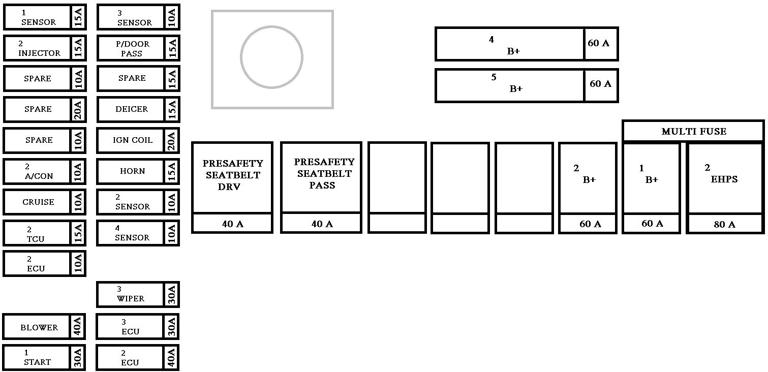
Engine compartment fuse panel (EMS BOX)
| Fuse name | Fuse rating | Circuit protected |
| F/PUMP | 15 | F/Pump Relay |
| ECU 4 | 15 | ECM/PCM |
| A/CON | 10 | A/CON COMP Relay |
| INJECTOR | 10 | Injector #1/#2/#3/#4, F/Pump Relay, A/CON COMP Relay |
| ECU 2 | 10 | ECM/PCM |
| IGN COIL 1 | 20 | Ignition Coil #1/#2/#3/#4, Condenser |
| SPARE | 20 | — |
| SENSOR 2 | 10 | Oxygen Sensor (Up), Oxygen Sensor (Down), Variable Intake Solenoid Valve, Oil Control Valve #1/#2 Purge Control Solenoid Valve, Canister Close Valve, E/R Fuse & Relay Box (C/Fan 1 Relay, C/Fan 2 Relay) |
| SENSOR 1 | 10 | Camshaft Position Sensor #1/#2 |
WARNING: Terminal and harness assignments for individual connectors will vary depending on vehicle equipment level, model, and market.