Chevrolet Impala mk10 (Tenth Generation) – from 2014 – fuse box diagram
Year of production: 2014, 2015, 2016
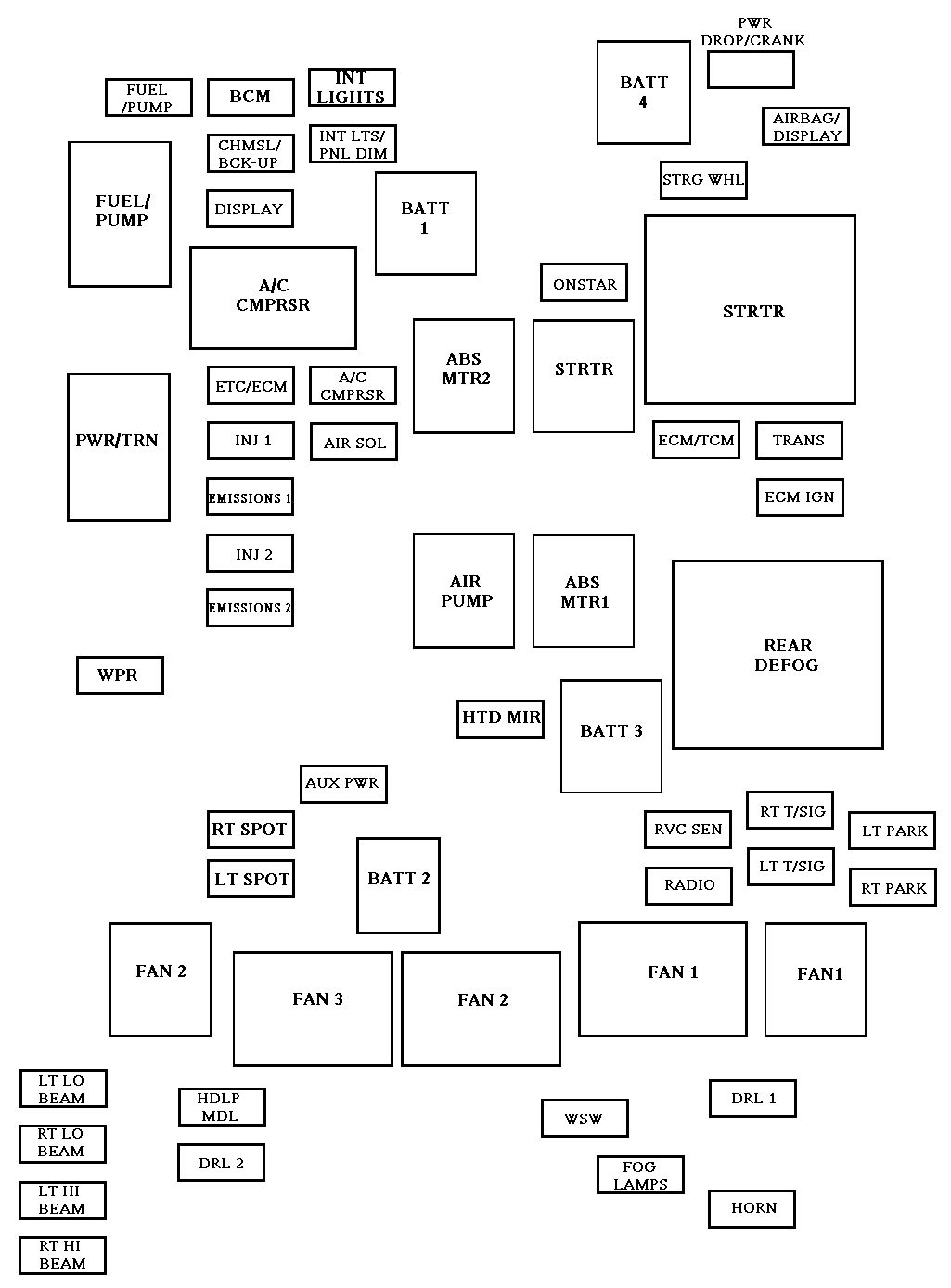
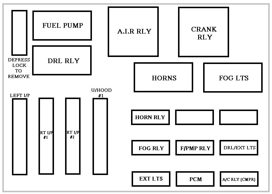
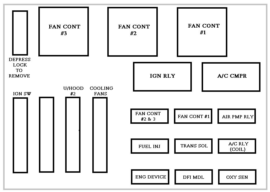
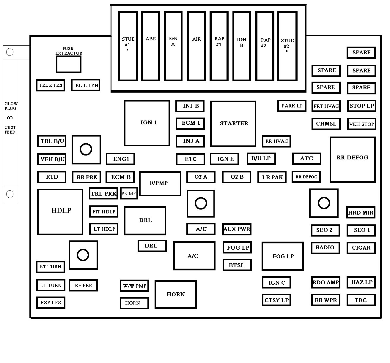
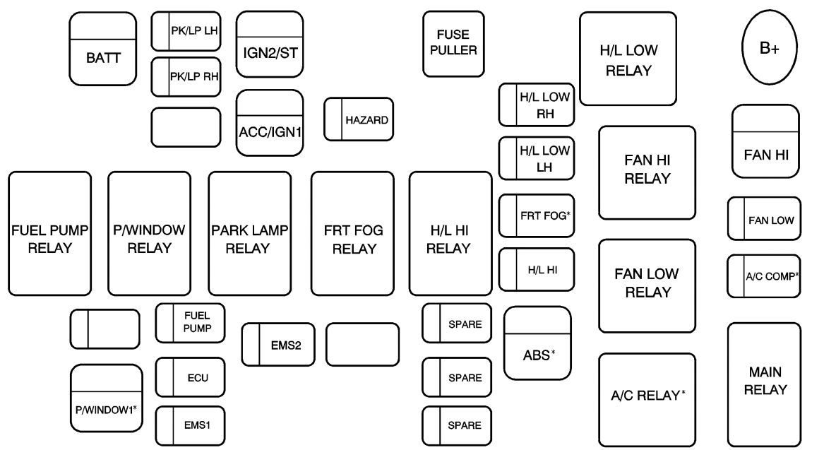
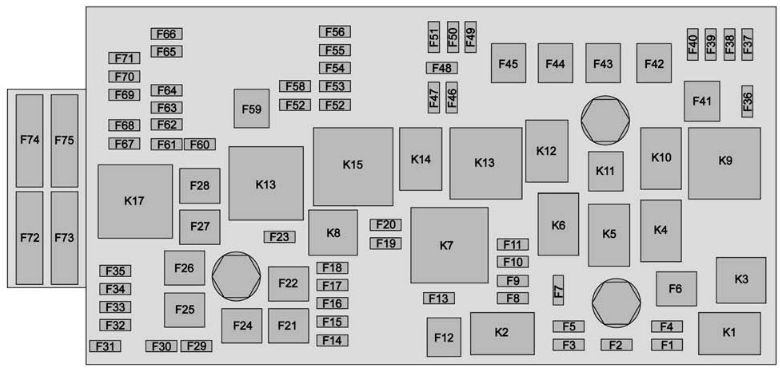
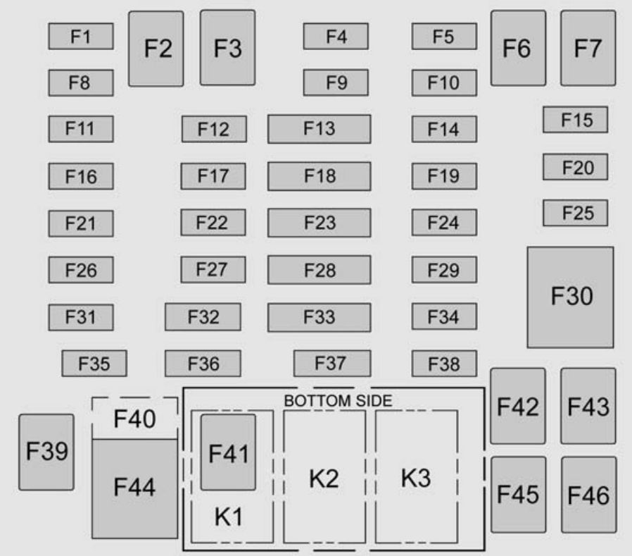
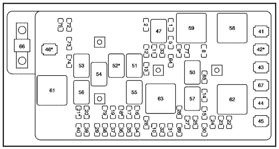
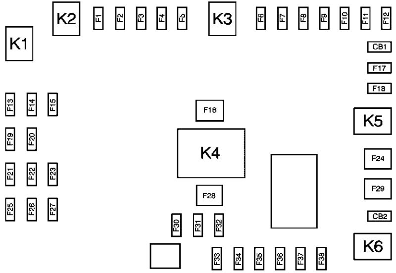
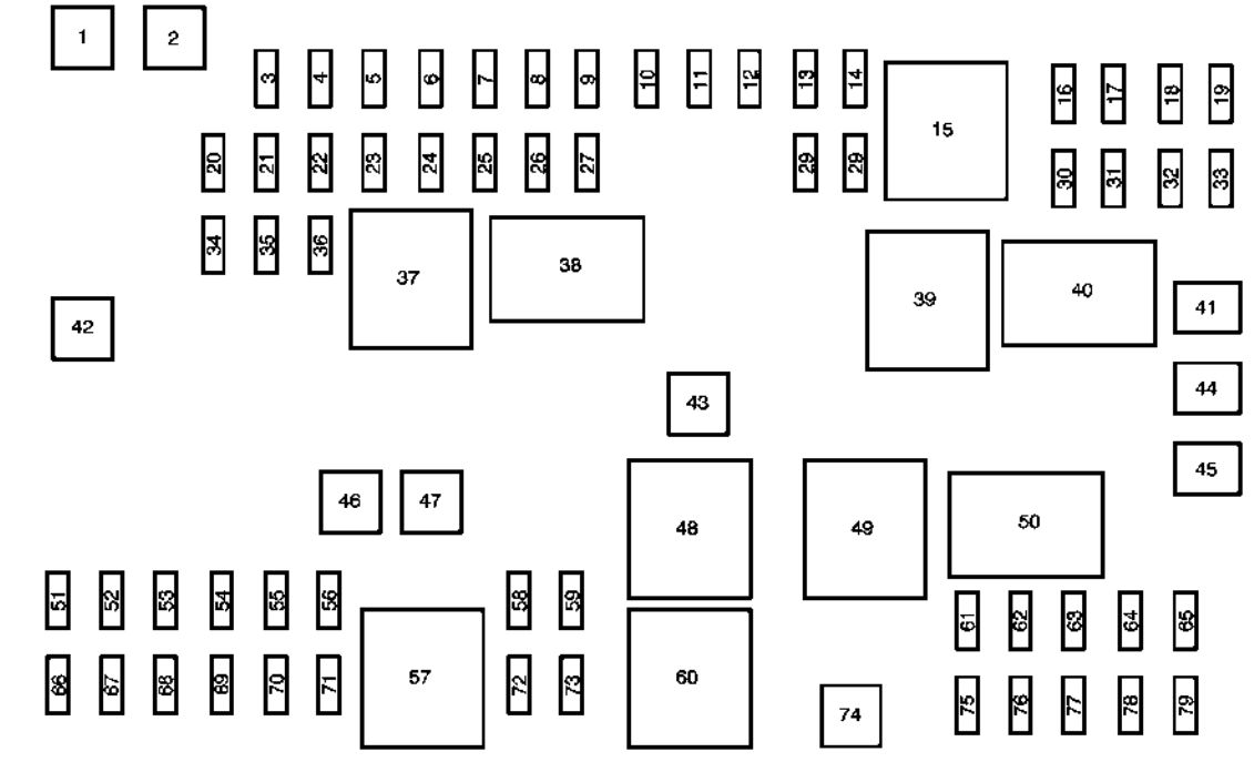
Engine Compartment Fuse Block
The engine compartment fuse block is on the driver side of the engine compartment, near the battery.
| Mini Fuses | Usage |
| 1 | Transmission Control Module Battery |
| 2 | Engine Control Module Battery |
| 3 | Air Conditioning Compressor Clutch |
| 4 | Engine Control Module BATT 1 |
| 5 | Engine Control Module Ignition |
| 7 | Cool Pump |
| 8 | Ignition Coils – Even |
| 9 | Ignition Coils – Odd |
| 10 | Engine Control Module |
| 11 | Emissions |
| 13 | Transmission Control Module/Chassis Control Module Ignition |
| 14 | SAIR Solenoid |
| 15 | Not Used |
| 16 | Aero Shutter |
| 17 | Seat Cooling Fans/ Heated Steering Wheel |
| 18 | Battery Disconnect Unit |
| 19 | Aero Shutter |
| 23 | Adaptive Cruise Control |
| 29 | Passive Entry/Passive Start Battery |
| 30 | Canister Vent Solenoid |
| 31 | Left Front Heated Seat |
| 32 | Right Rear Stop. Turn Tail Lamp, RAP Relay, Ambient Lighting Control, Interior Switch Backlighting |
| 33 | Right Front Heated Seat |
| 34 | Antilock Brake System Valve |
| 35 | Amplifier |
| 37 | Right High Beam |
| 38 | Left High Beam |
| 46 | Cooling Fan |
| 47 | Emissions |
| 48 | Not Used |
| 49 | Right HID Lighting |
| 50 | Left HID Lighting |
| 51 | Horn/Dual Horn |
| 52 | Cluster Ignition |
| 53 | Inside Rearview Mirror/Rear Camera |
| 54 | Reflected LED Display, Console LED Display, Heating, Ventilation and Air Conditioning Module |
| 55 | Outside Rearview Mirror |
| 56 | Windshield Washer |
| 60 | Heated Mirror |
| 62 | Rear Camera/Park Assist/Side Blind Zone Alert |
| 66 | Trunk Release |
| 67 | Chassis Control Module |
| 69 | Battery Voltage Sensor |
| 70 | Not Used |
| 71 | Memory Seat |
| J-Case Fuses | Usage |
| 6 | Front Wiper |
| 12 | Starter |
| 21 | Rear Power Window |
| 22 | Sunroof |
| 24 | Front Power Window |
| 25 | Accessory Relay |
| 26 | Antilock Brake System Pump |
| 27 | Electric Parking Brake |
| 28 | Rear Defogger |
| 41 | Vacuum Pump |
| 42 | Cooling Fan K2 |
| 44 | Transmission Auxiliary Pump (eAssist) |
| 45 | Cooling Fan K1 |
| 59 | Air Pump Emissions |
| Mini Relays | Usage |
| 7 | Powertrain |
| 9 | Cooling Fan K2 |
| 13 | Cooling Fan K1 |
| 15 | Run/Crank |
| 16 | Air Pump Emissions |
| 17 | Window/Mirror Defogger |
| Micro Relays | Usage |
| 1 | Air Conditioning Compressor Clutch |
| 2 | Starter Solenoid |
| 4 | Front Wiper Speed |
| 5 | Front Wiper Control |
| 6 | Air Pump Solenoid Emissions/Cabin Pump (eAssist) |
| 10 | Cooling Fan K3 |
| 11 | Transmission Oil Pump (eAssist) |
| 14 | Low Beam HID |
| 22 | Air Pump Solenoid Emissions (eAssist) |
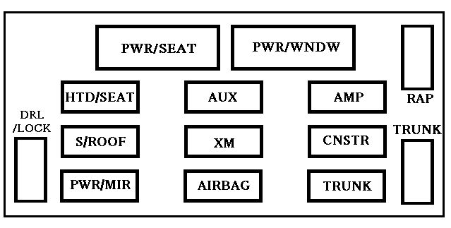
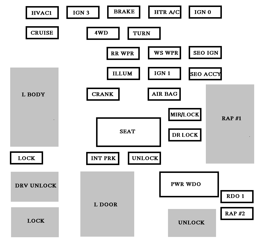
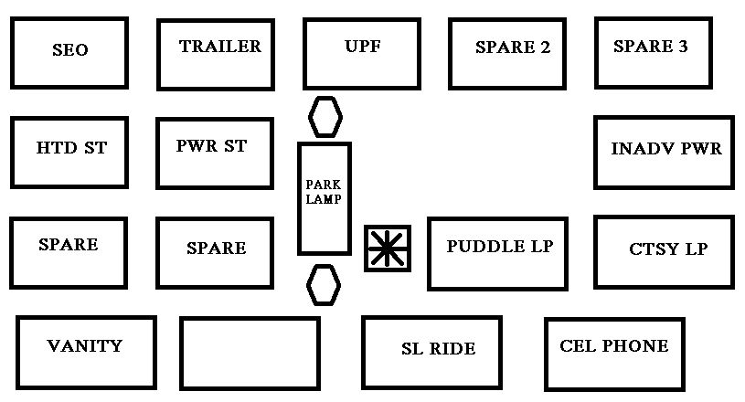
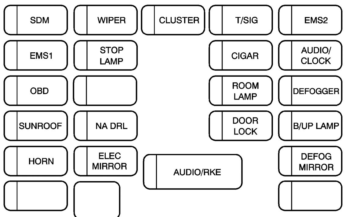
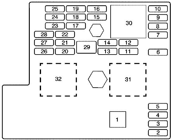
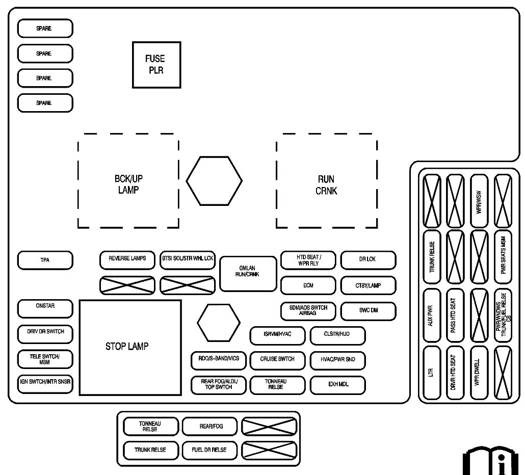
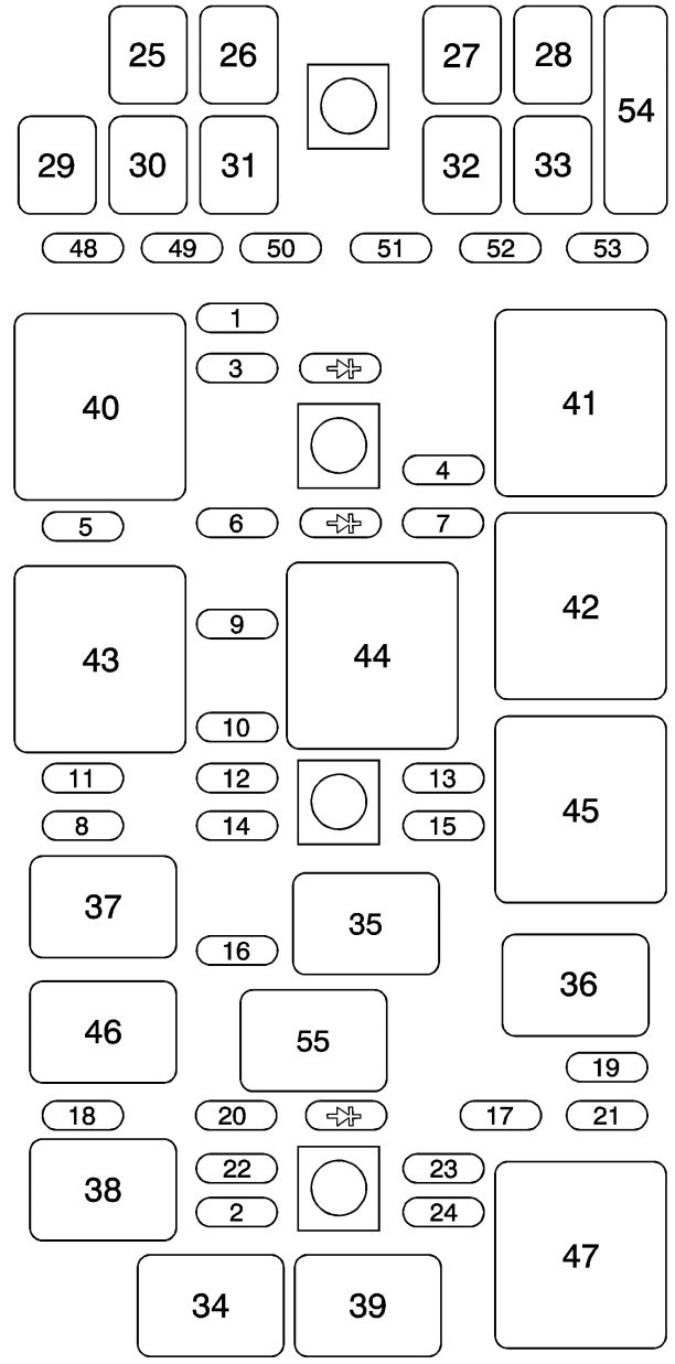
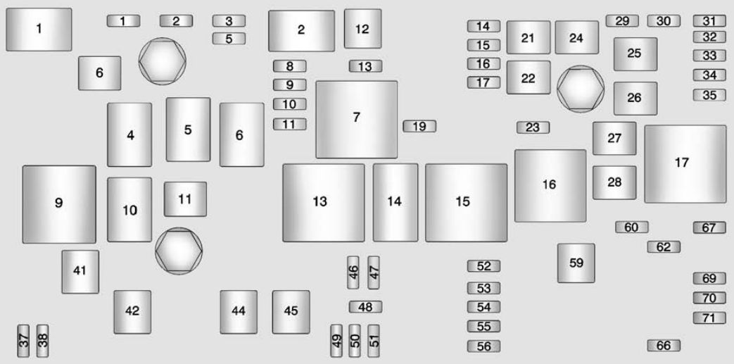
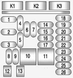
Instrument Panel Fuse Block
The instrument panel fuse block is in the instrument panel, on the driver side of the vehicle.
| Mini Fuses | Usage |
| 1 | Telematics |
| 2 | Rear Turn Stoplamp, Courtesy Lamps, Back-up Lamps, Shift Lock Solenoid, Puddle Lamps |
| 3 | LED Indicator Light |
| 4 | Radio |
| 5 | Display |
| 6 | Power Outlet – Console Bin |
| 7 | Power Outlet – Forward/ Console Rear |
| 8 | Trunk Release, Brake Pedal Apply, Keyless Start Indicators, Hazard Switch Illumination, CHMSL/Brake Relay, Sidemarker Lamps, Washer Relay, Run/Crank Relay |
| 9 | Trunk Lamp, Right Low Beam/DRL, Right Front Turn Lamp, Right Rear Park/Stoplamp |
| 14 | Diagnostic Link Connector |
| 15 | Airbag/SDM |
| 16 | Not Used |
| 17 | Heater, Ventilation and Air Conditioning Controller |
| 18 | Logistics |
| 19 | Not Used |
| 20 | Ignition Switch |
| 21 | Not Used |
| 22 | Steering Wheel Controls |
| 23 | Left Low Beam/DRL, Left Front Turn Lamp, Left Rear Park/Stoplamp, Child Lock Relay |
| 24 | Theft Deterrent LED, Key Capture Solenoid, Run Relay |
| 25 | Tilt/Telescope Steering Column |
| 26 | 110V AC |
| J–Case Fuses | Usage |
| 10 | Door Unlock |
| 11 | Front Heater, Ventilation, and Air Conditioning Blower |
| Circuit Breakers | Usage |
| 12 | Power Seat– Passenger |
| 13 | Power Seat–Driver |
| Relays | Usage |
| K1 | Not Used |
| K2 | Logistic |
| K3 | Power Outlet Relay |
WARNING: Terminal and harness assignments for individual connectors will vary depending on vehicle equipment level, model, and market.