Fiat 500 (2010 – 2014) – fuse box diagram
Year of production: 2010, 2011, 2012, 2013, 2014
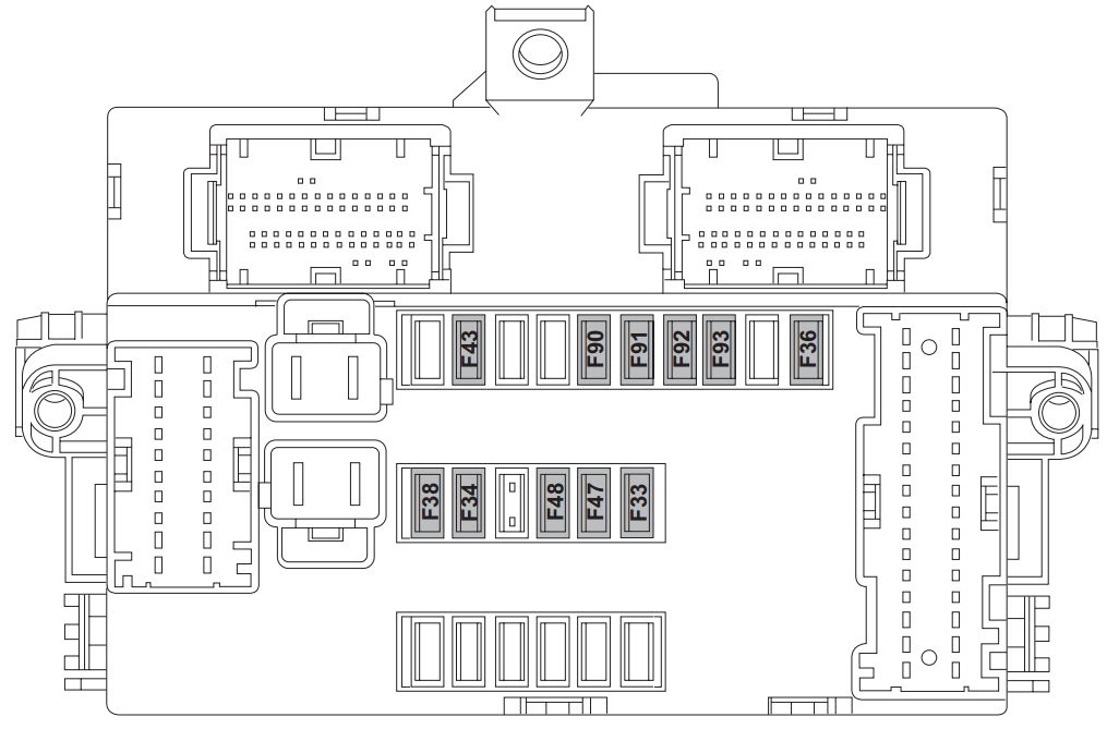
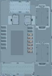
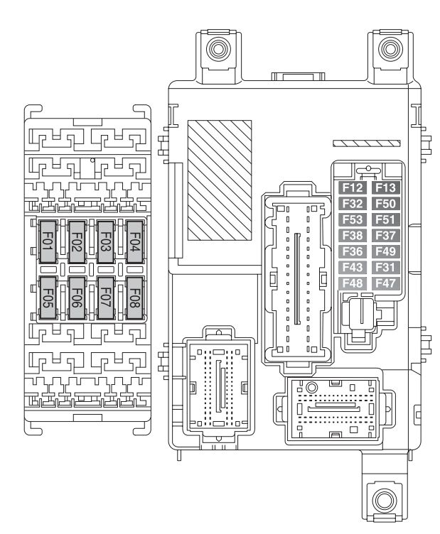
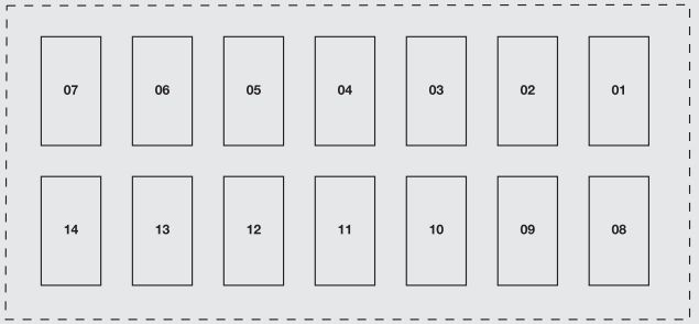
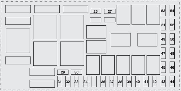
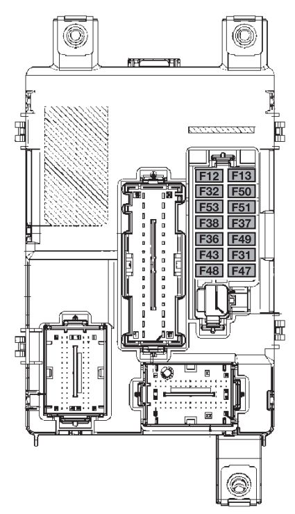
Fuse box in dashboard
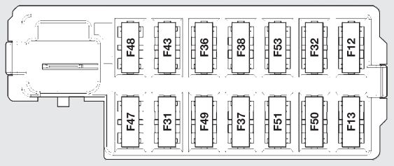
| Fuse | Fuse | Ampere rating [A] |
| Supply of right low beam | F12 | 7,5 |
| Supply of left low beam and headlamp direction adjustment control unit | F13 | 7,5 |
| Lights of front and rear ceiling lights, trunk and door courtesy lights | F32 | 7,5 |
| Diagnostic socket, car radio, climate control system, EOBD | F36 | 10 |
| Stop lights switch, instrument panel node | F37 | 5 |
| Door central locking | F38 | 20 |
| Windshield/Rear windshield washer pump | F43 | 15 |
| Driver side power window | F47 | 20 |
| Passenger side power window | F48 | 20 |
| Parking sensor, backlighting switches, electric mirrors | F49 | 5 |
| Car radio switch, convergence, climate control system, stop lights, clutch | F51 | 7,5 |
| Instrument panel node | F53 | 5 |
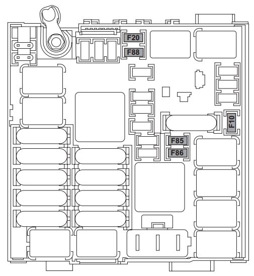
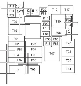
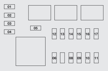
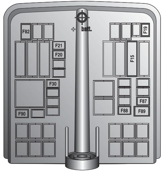
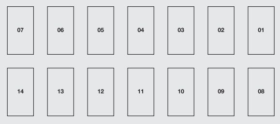
Fuse box in engine compartment
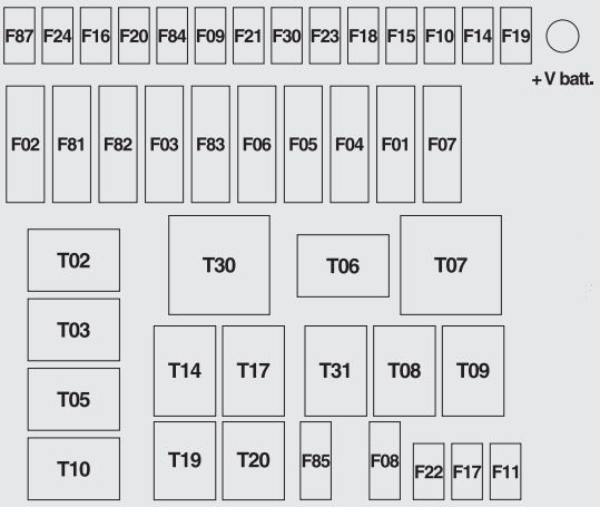
| Description | Fuse | Ampere rating [A] |
| Climate control system fan | F08 | 30 |
| Trailer | F09 | 15 |
| Buzzers | F10 | 15 |
| Engine control system (secondary loads) | F11 | 10 |
| Main headlights | F14 | 15 |
| Sunroof motor | F15 | 20 |
| Heated rear window, mirror demisters | F20 | 30 |
| Fog headlights | F30 | 15 |
| Front socket (with or without cigar lighter plug) | F85 | 15 |
Article about Fiat 500 (2007 – 2010) include description every fuses and relays from diagram. If you looking it, you can check it here.
WARNING: Terminal and harness assignments for individual connectors will vary depending on vehicle equipment level, model, and market.