Mercury Sable 5th (Fifth) Generation (2008 – 2009) – fuse box diagram
Year of production: 2008, 2009
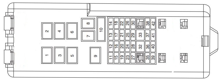
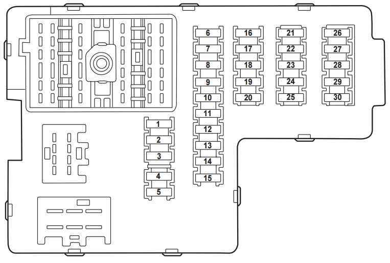
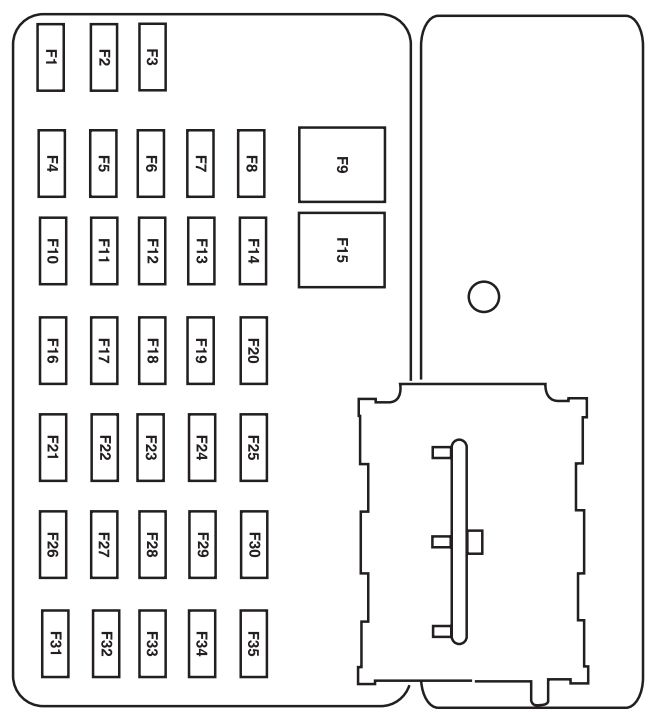
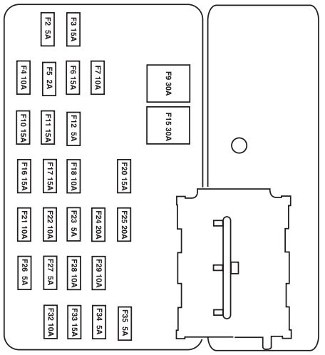
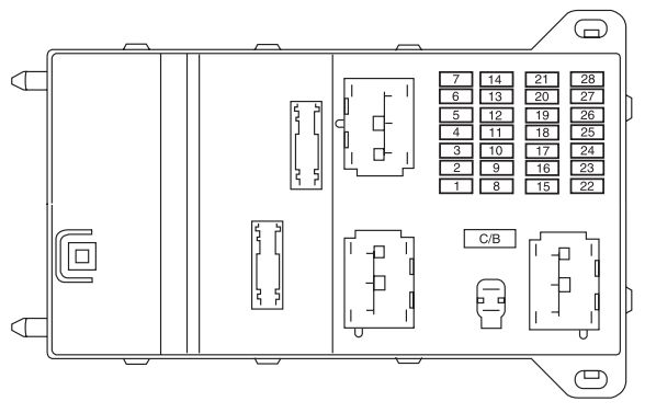
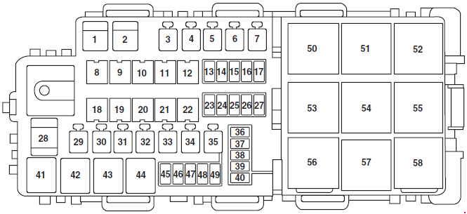
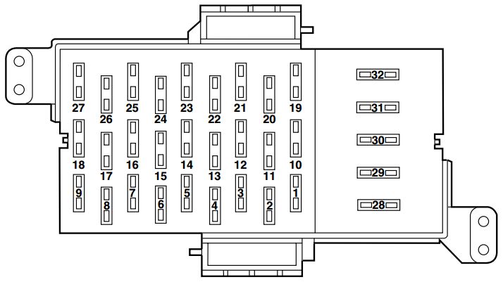
Passenger compartment fuse panel
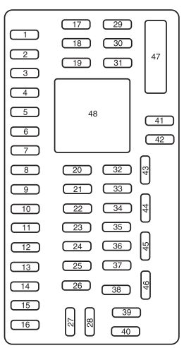
The fuse panel is located under the instrument panel to the left of the steering wheel.
| Fuse/relay | Ampere rating [A] | Description |
| 1 | 30 | Smart window motor |
| 2 | 15 | Brake on/off switch, High-mounted brake lamp |
| 3 | 15 | SDARS, Bluetooth, Family entertainment system (FES)/Rear seat control |
| 4 | 30 | Spare |
| 5 | 10 | SPDJB logic power |
| 6 | 20 | Turn signals |
| 7 | 10 | Low beam headlamps (left) |
| 8 | 10 | Low beam headlamps (right) |
| 9 | 15 | Interior lights, Cargo lamps |
| 10 | 15 | Backlighting, Puddle lamps |
| 11 | 10 | All wheel drive |
| 12 | 7,5 | Memory seat/mirror switches, Memory module |
| 13 | 5 | FEPS module |
| 14 | 10 | Analog clock |
| 15 | 10 | Climate control |
| 16 | 15 | Spare |
| 17 | 20 | All power lock motor feeds, Decklid release |
| 18 | 20 | Spare |
| 19 | 25 | Moon roof |
| 20 | 15 | OBDII connector |
| 21 | 15 | Fog lamps |
| 22 | 15 | Park lamps, License lamps |
| 23 | 15 | High beam headlamps |
| 24 | 20 | Horn relay |
| 25 | 10 | Demand lamps/Interior lamps |
| 26 | 10 | Instrument panel cluster |
| 27 | 20 | Adjustable pedal switch |
| 28 | 5 | Radio, Radio start signal |
| 29 | 5 | Instrument panel cluster |
| 30 | 5 | Overdrive cancel switch |
| 31 | 10 | Compass, Automatic dimming rear view mirror |
| 32 | 10 | Restraint control module |
| 33 | 10 | Spare |
| 34 | 5 | AWD module |
| 35 | 10 | Steering rotation sensor, FEPS, Rear park assist, Heated seat modules |
| 36 | 5 | PATS module |
| 37 | 10 | Climate control |
| 38 | 20 | Subwoofer (Audiophile radio) |
| 39 | 20 | Radio |
| 40 | 20 | Spare |
| 41 | 15 | Mic mirror, Moon roof, Front lock switches, Radio |
| 42 | 10 | Spare |
| 43 | 10 | Spare |
| 44 | 10 | Spare |
| 45 | 5 | Relay coils: PDB, Auxiliary A/C, Front and rear wipers, Front blower motor |
| 46 | 5 | Occupant Classification Sensor (OCS), Passenger Airbag Deactivation Indicator (PADI) |
| 47 | 30 Circuit Breaker | Power windows |
| 48 | — | Delayed accessory relay |
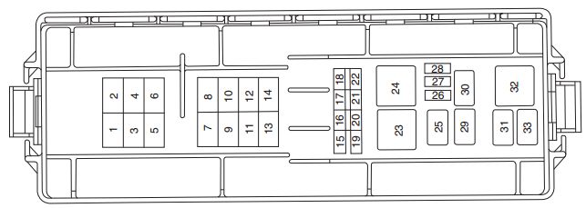
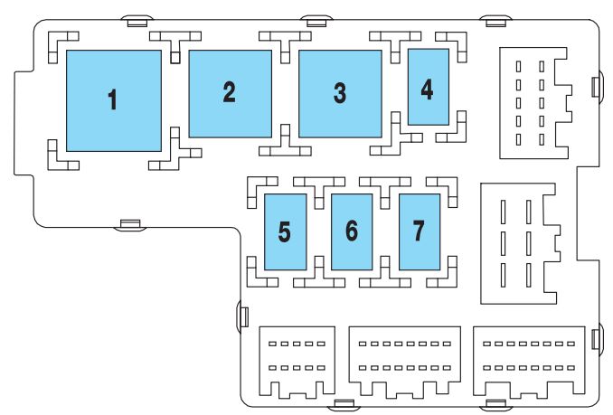
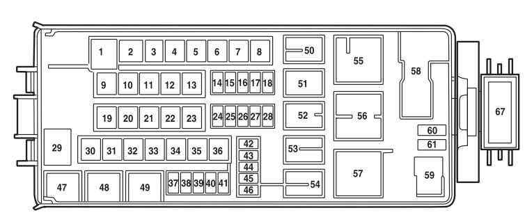
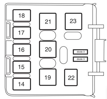
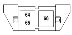
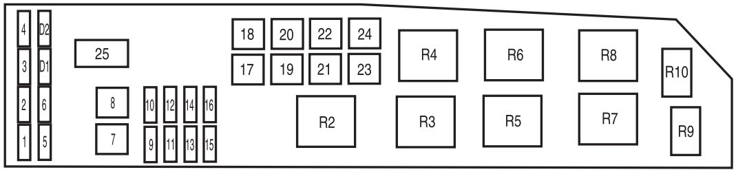
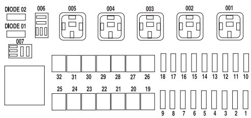
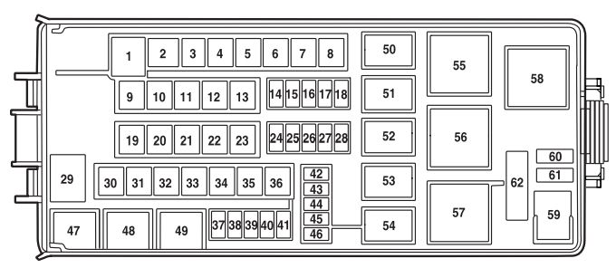
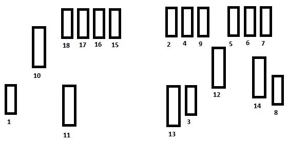
Power distribution box
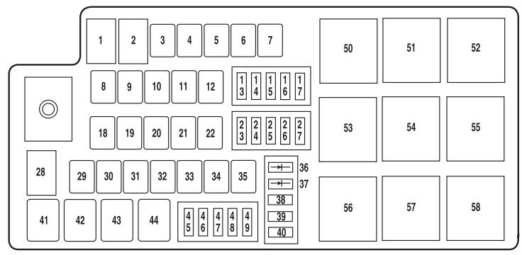
The power distribution box is located in the engine compartment
| Fuse/relay | Ampere rating [A] | description |
| 1 | 80* | SPDJB power |
| 2 | 80* | SPDJB power |
| 3 | 30* | Front wipers |
| 4 | — | Not used |
| 5 | 20 | Spare |
| 6 | — | Not used |
| 7 | 50* | Engine cooling fan |
| 8 | — | Not used |
| 9 | 40* | Anti-lock Brake System (ABS)/AdvanceTrac pump |
| 10 | 30* | Starter |
| 11 | 50* | Powertrain Control Module (PCM) relay |
| 12 | 20* | ABS/AdvanceTrac valve |
| 13 | 20** | Power point (instrument panel) |
| 14 | 20** | Power point (2nd row) |
| 15 | 20 | Spare |
| 16 | 20** | Power point (console) |
| 17 | 10** | Alternator |
| 18 | — | Not used |
| 19 | — | Not used |
| 20 | 40* | Rear defroster |
| 21 | 30* | Power seat motors (passenger) |
| 22 | 20* | Heated seat module |
| 23 | 10* | PCM Keep alive power, Canister vent |
| 24 | 10** | A/C clutch relay |
| 25 | 25 | Spare |
| 26 | 20** | Backup relay |
| 27 | 15** | Fuel relay (Fuel pump driver module, Fuel pump) |
| 28 | — | Not used |
| 29 | 30 | Spare |
| 30 | — | Not used |
| 31 | 30* | Spare |
| 32 | 30* | Driver seat motors, Memory module |
| 33 | 20* | Ignition switch (to SJB) |
| 34 | — | Not used |
| 35 | 40* | Front A/C blower motor |
| 36 | 1A Diode | One-touch start |
| 37 | 1A Diode | Fuel pump |
| 38 | 10** | IVD, Yaw rate sensor |
| 39 | 10** | Fuel diode, PCM |
| 40 | — | Not used |
| 41 | G8VA relay | A/C clutch |
| 42 | G8VA relay | Fuel pump |
| 43 | G8VA relay | Backup |
| 44 | — | Not used |
| 45 | 10** | Speed control deactivate switch, Mass air flow sensor, Inline module VPWR2 |
| 46 | 10** | A/C clutch relay, VPWR3 |
| 47 | 15** | PCM VPWR1 |
| 48 | 15** | PCM VPWR4 |
| 49 | 15** | Heated mirrors |
| 50 | Full ISO relay | PCM relay |
| 51 | — | Not used |
| 52 | — | Not used |
| 53 | Full ISO relay | Rear defrost relay |
| 54 | Full ISO relay | Blower motor relay |
| 55 | Full ISO relay | Starter relay |
| 56 | — | Not used |
| 57 | Full ISO relay | Front wiper relay |
| 58 | — | Not used |
| * Cartridge Fuses ** Mini Fuses | ||
WARNING: Terminal and harness assignments for individual connectors will vary depending on vehicle equipment level, model, and market