Year of production: 2008, 2009, 2010, 2011, 2012, 2013, 2014, 2015, 2016
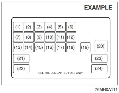
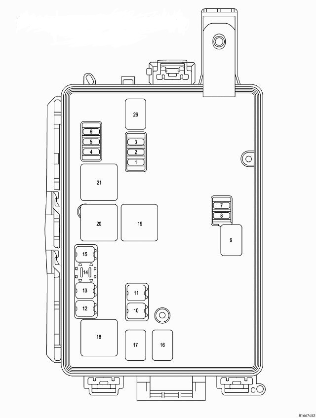
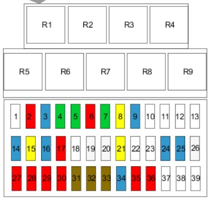
SRT8 Integrated power module (front engine bay)
Dodge Challenger RT/SRT Third Generation – integrated power module
Cavity
Cartridge fuse [A]
Mini-fuse [A]
Description
1
—
15 Blue
Washer Motor
2
—
25 Neutral
Powertrain Control Module (PCM)
3
—
25 Neutral
Ignition Run/Start
4
—
25 Neutral
Alternator
5
—
—
—
6
—
25 Neutral
Ignition Coils/Injectors
7
—
—
—
8
—
25 Neutral
Starter
9
—
—
—
10
30 Pink
—
Windshield Wiper
11
30 Pink
—
Anti-lock Brake System (ABS) Valves
12
40 Green
—
Radiator fan
13
50 Red
—
Anti-lock Brake System (ABS) Pump Motor
14
—
—
—
15
50 Red
—
Radiator fan
16
—
—
—
17
—
—
—
18
—
—
—
19
—
—
—
20
—
—
—
21
—
—
—
22
—
—
—
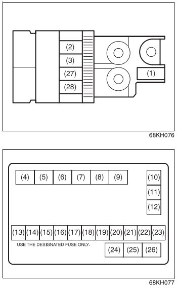
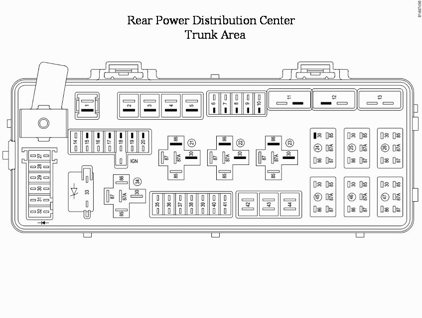
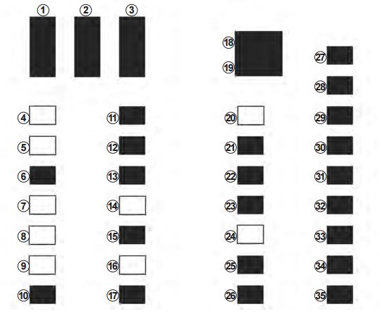
Rear power distribution center fuses – RT/SRT (trunk area)
Dodge Challenger RT/SRT Third Generation – fuse box – rear power distribution – ceneter trunk area
Cavity
Cartridge fuse [A]
Mini fuse [A]
Description
1
60 Yellow
—
Ignition Off Draw (IOD)
2
40 Green
—
Integrated Power Module (IPM)
3
—
—
—
4
40 Green
—
Integrated Power Module (IPM)
5
30 Pink
—
Heated Seats – if equipped
6
—
20 Yellow
Fuel Pump
7
—
20 Yellow
Sub Amp – if equipped
8
—
15 Blue
Diagnostic Link Connector (DLC)/Wireless Ignition Node (WIN)
9
—
20 Yellow
Power Outlet
10
—
—
—
11*
—
—
—
12*
—
—
—
13*
—
—
—
14
—
10 Red
AC Heater Control/Cluster/Security Module – if equipped
15
—
20 Yellow
—
16
—
20 Yellow
—
17
—
20 Yellow
Cluster
18
—
20 Yellow
Selectable Power Outlet
19
—
10 Red
Stop Lights
20
—
—
—
21
—
—
—
22
—
—
—
23
—
—
—
24
—
—
—
25
—
—
—
26
—
—
—
27
—
10 Red
Occupant Restraint Controller (ORC)
28
—
10 Red
Ignition Run
29
—
5 Orange
Cluster/Electronic Stability Program (ESP)/Powertrain Control Module (PCM)/STOP LIGHT Switch
30
—
10 Red
Door Modules/Power Mirrors/Steering Control Module (SCM)
31
—
—
—
32
—
—
—
33
—
—
—
34
—
—
—
35
—
5 Orange
Antenna Module – if equipped/Power Mirrors/Rain Sensor – if equipped
36
—
20 Yellow
Hands-Free Phone – if equipped/Video Monitor – if equipped/Radio
37
—
15 Blue
Transmission
38
—
10 Red
Cargo Light/Vehicle Information Module – if equipped
39
—
10 Red
Heated Mirrors – if equipped
40
—
5 Orange
Auto Inside Rearview Mirror/Heated Seats – if equipped/Switch Bank
41
—
10 Red
AC Heater Control/Headlights/Park Assist – if equipped/Tire Pressure Monitoring – if equipped/Occupant Restraint Controller (ORC)
42
30 Pink
—
Front Blower Motor
43
30 Pink
—
Rear Window Defroster
44
20 Blue
—
Amplifier – if equipped/Sunroof – if equipped
The Cluster (without power memory seat), the Driver Seat Switch (with power memory seat), and the Memory Module
(if equipped) are fused by the 25 amp circuit breaker in Cavity 11.
The Passenger Seat Switch is fused by the 25 amp circuit breaker in Cavity 12. The Door Modules (except base), the
Driver Door Lock Switch (base), the Driver Express Power Window Switch (if equipped), and the Passenger Door
Lock Switch (base) are fused by the 25 amp circuit breaker in Cavity 13.
WARNING: Terminal and harness assignments for individual connectors will vary depending on vehicle equipment level, model, and market.
Ignition Off Draw (IOD) Cavity 1 of the Rear Power Distribution Center contains a black IOD fuse needed for vehicle processing during assembly. The service replacement part is a 60 Amp yellow cartridge fuse.
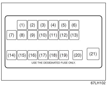
2
40 Green
—
Integrated Power Module (IPM)
3
—
—
—
4
40 Green
—
Integrated Power Module (IPM)
5
30 Pink
—
Heated Seats – If Equipped
6
—
20 Yellow
Fuel Pump
7
—
15 Blue
Sub Amp – If Equipped
8
—
15 Blue
Diagnostic Link Connector (DLC)/Wireless Control Module (WCM)/ Wireless Ignition Node (WIN)
9
—
20 Yellow
Power Outlet
10
—
—
—
11*
—
—
—
12*
—
—
—
13*
—
—
—
14
—
10 Red
AC Heater Control/ Cluster/Security Module – If Equipped
15
—
—
—
16
—
—
—
17
—
20 Yellow
Cluster
18
—
20 Yellow
Selectable Power Outlet
19
—
10 Red
Stop Lights
20
—
—
—
21
—
—
—
22
—
—
—
23
—
—
—
25
—
—
—
26
—
—
—
27
—
10 Red
Occupant Restraint Controller (ORC)
28
—
10 Red
Ignition Run, AC Heater Control/Occupant Restraint Controller (ORC)
29
—
5 Orange
Cluster/Electronic Stability Program (ESP)/ Powertrain Control Module (PCM)/STOP LIGHT Switch
30
—
10 Red
Door Modules/Power Mirrors/Steering Control Module (SCM)
31
—
—
—
32
—
—
—
33
—
—
—
34
—
—
—
35
—
5 Orange
Antenna Module – If Equipped/Power Mirrors
36
—
25 Netural
Hands-Free Phone – If Equipped/Radio/ Amplifier Feed
37
—
15 Blue
Transmission
38
—
10 Red
Cargo Light/Vehicle Information Module – If Equipped
39
—
10 Red
Heated Mirrors – If Equipped
40
—
5 Orange
Auto Inside Rearview Mirror/Heated Seats – If Equipped/Switch Bank
41
—
—
—
42
30 Pink
—
Front Blower Motor
43
30 Pink
—
Rear Window Defroster
44
20 Blue
—
Amplifier/Sunroof – If Equipped
WARNING: Terminal and harness assignments for individual connectors will vary depending on vehicle equipment level, model, and market.