Ford Mondeo Vignale (from 2015) – fuse box (EU version)
Year of production: 2015, 2016
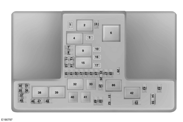
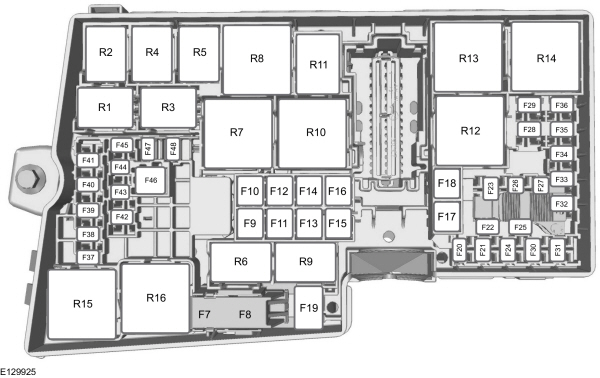
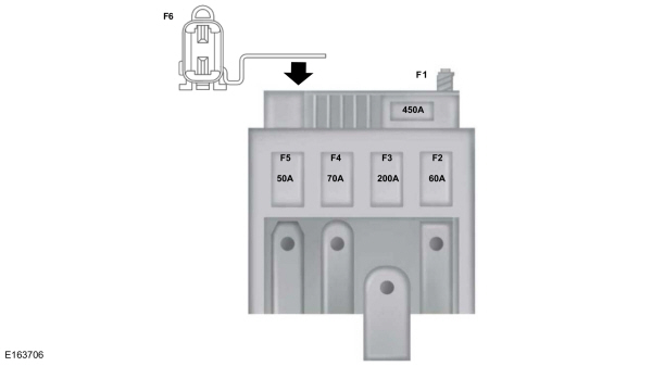
Power Distribution Box

| Fuse or relay number | Ampere rating [A] | Protected components |
| 1 | 25*** | Windshield wipers |
| 2 | — | Starter relay |
| 3 | 15* | Autowipers. Rear wiper |
| 4 | — | Blower motor relay |
| 5 | 20*** | Back of console auxiliary power point |
| 6 | — | Auxiliary heater relay |
| 7 | 20* | Powertrain control module |
| 8 | 20* | Powertrain control module |
| 9 | — | Powertrain control module relay |
| 10 | 20*** | Driver front auxiliary power point |
| 11 | 15** | Powertrain control module |
| 12 | 15** | Powertrain control module |
| 13 | 10** | Powertrain control module |
| 14 | 10** | Powertrain control module |
| 15 | — | Run-start relay |
| 16 | 20*** | Console auxiliary power point |
| 17 | 20*** | Auxiliary power point |
| 18 | 10* | Powertrain control module |
| 19 | 10* | Power steering |
| 20 | 10* | Run-start lighting |
| 21 | 15* | Transmission control module. Transmission oil pump |
| 22 | 10* | Air conditioning |
| 23 | 15* | Blind spot monitor. Rear view camera. Adaptive Cruise Control. Pre-collision warning indicator. Voltage quality module. Air quality sensor |
| 24 | 10* | Not used (spare) |
| 25 | 10** | Anti-lock brake system |
| 26 | 10** | Powertrain control module |
| 27 | 10* | Not used (spare) |
| 28 | 10* | Rear washer pump |
| 29 | — | Not used |
| 30 | — | Not used. |
| 31 | — | Not used. |
| 32 | — | Cooling fan relay |
| 33 | — | Air conditioning relay |
| 34 | 15* | Electric steering column lock |
| 35 | — | Not used |
| 36 | — | Not used |
| 37 | — | Not used |
| 38 | — | Cooling fan relay |
| 39 | — | Cooling fan relay |
| 40 | — | Not used |
| 41 | — | Horn relay |
| 42 | — | Fuel pump relay |
| 43 | — | Not used |
| 44 | 5* | Heated washer nozzle |
| 45 | — | Not used |
| 46 | 10** | Alternator. |
| 47 | 10** | Brake on-off switch |
| 48 | 20* | Horn |
| 49 | 5* | Mass air flow monitor |
| 20** | Fuel heater element-Diesel | |
| 50 | 10* | Power transfer unit cooling fan |
| 51 | — | Not used |
| 52 | — | Not used |
| 53 | 10* | Power seats |
| 54 | 5** | Fuel operated heater remote control |
| 55 | 5** | Not used (spare) |
|
*Micro fuse.
**Dual micro fuse.
***M-type fuse.
|
||
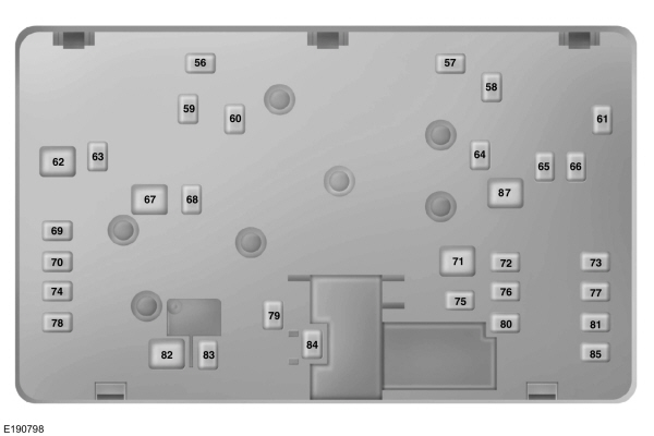
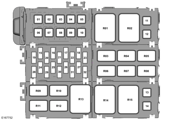
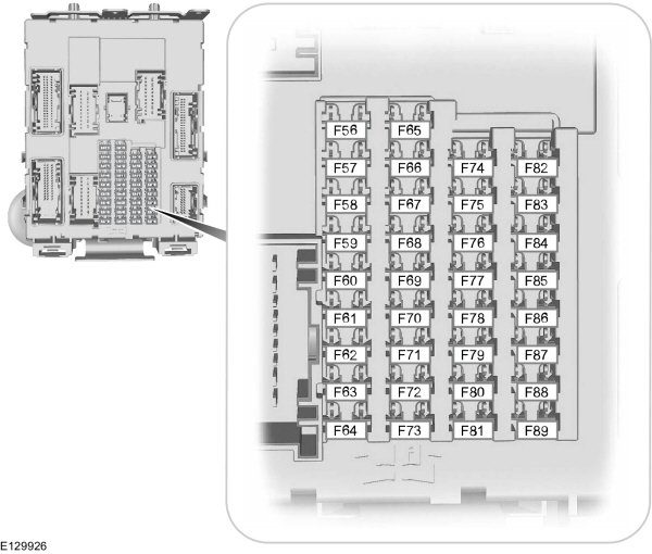
Power distribution box – bottom

| Fuse or relay number | Ampere rating [A] | Protected components |
| 56 | — | Not used |
| 57 | 20* | Diesel vaporizer |
| 58 | 30* | Fuel pump |
| 59 | 30** | Cooling fan |
| 40** | Cooling fan (DW10F and 2.0L GTDI AU) | |
| 60 | 30* | Cooling fan |
| 40** | Cooling fan (DW10F and 2.0L GTDI AU) | |
| 61 | 40* | Left-hand heated windshield element |
| 62 | 50** | Body control module |
| 63 | 25* | Cooling fan |
| 30* | Cooling fan (DW10F and 2.0L GTDI AU) | |
| 64 | 30* | Auxiliary heater |
| 65 | 20* | Front heated seat |
| 66 | 40* | Right-hand heated windshield element |
| 67 | 50** | Body control module |
| 68 | 40* | Heated rear window |
| 69 | 30* | Anti-lock brake system |
| 70 | 30* | Passenger seat |
| 71 | 60** | Auxiliary heater |
| 72 | 30* | Moonroof |
| 73 | 20* | Rear heated seat |
| 74 | 30* | Driver seat module |
| 75 | 30* | Auxiliary heater |
| 76 | 20* | Transmission oil pump |
| 77 | 30* | Climate control seat module |
| 78 | 40* | Trailer tow module |
| 79 | 40* | Blower motor |
| 80 | 30* | Power luggage compartment module |
| 81 | 40* | 220 volt inverter |
| 82 | 60** | Anti-lock brake system pump |
| 83 | 25* | Wiper motor |
| 84 | 30* | Starter solenoid |
| 85 | 20* | Fuel fire heater |
|
*M-type fuse.
*J-type fuse
|
||
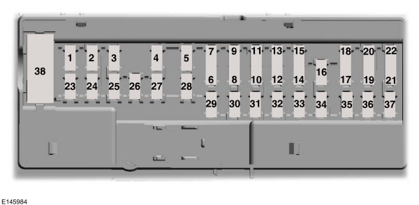
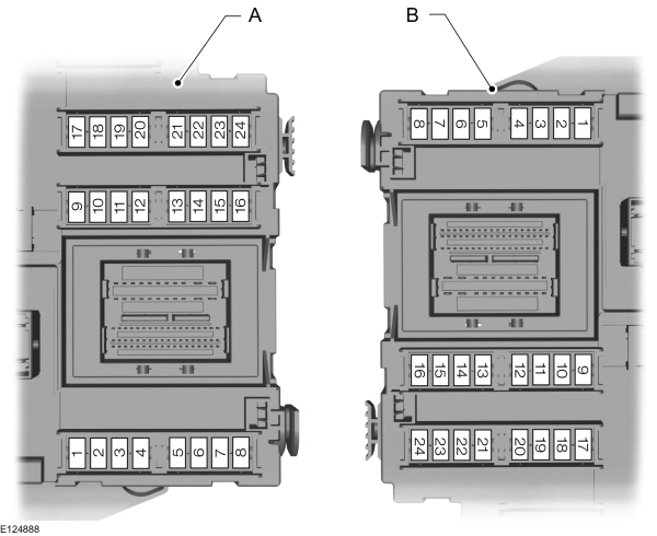
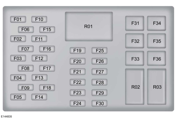
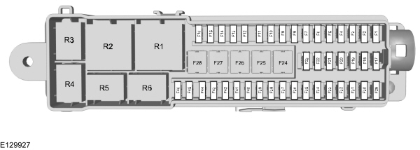
Passenger compartment fuse panel

| Fuse or relay number | Ampere rating [A] | Protected components |
| 1 | 10* | Ambient lighting. Glove box lamp. Vanity lamp. Dome lamp. Luggage compartment lamp |
| 2 | 7,5* | Memory seat. Driver seat lower back support. Power exterior mirrors |
| 3 | 20* | Driver door unlock |
| 4 | 5* | Not used (spare) |
| 5 | 20* | Not used (spare) |
| 6 | 10** | Not used (spare) |
| 7 | 10** | Not used (spare) |
| 8 | 10** | Anti-theft alarm horn |
| 9 | 10** | Not used (spare) |
| 10 | 5** | Power liftgate module |
| 11 | 5** | Combined security module |
| 12 | 7,5** | Climate control |
| 13 | 7,5** | Steering wheel column. Instrument cluster. Data link connector |
| 14 | 10** | Not used (spare) |
| 15 | 10** | Data link gateway |
| 16 | 15* | Child lock. Luggage compartment-liftglass release |
| 17 | 5** | Battery backup sounder |
| 18 | 5** | Ignition switch. Push button ignition switch |
| 19 | 5** | Passenger airbag deactivation indicator. Transmission |
| 20 | 5** | Headlamp control module |
| 21 | 5** | Passenger compartment thermometer |
| 22 | 5** | Not used (spare) |
| 23 | 10* | Delayed accessory power |
| 24 | 20* | Lock-unlock |
| 25 | 30* | Driver door window. Driver door mirror |
| 26 | 30* | Front passenger door window. Front passenger door mirror |
| 27 | 30* | Moonroof |
| 28 | 20* | Audio amplifier |
| 29 | 30* | Rear driver side door window |
| 30 | 30* | Rear passenger side door window |
| 31 | 15* | Not used (spare) |
| 32 | 10* | Global positioning system module. Voice control. Information and entertainment display. Radio frequency receiver |
| 33 | 20* | Radio. Active noise control. |
| 34 | 30* | Run/start bus (fuse #19, 20, 21, 22, 35, 36, 37, circuit breaker) |
| 35 | 5* | Restraints control module |
| 36 | 15* | Auto-dimming interior mirror. Front and rear heated seat module. CCD module. Lane keeping system module. Auto high beam. Climate controlled seats |
| 37 | 15* | All wheel drive module. Heated steering wheel |
| 38 | 30 | Not used (spare) |
|
*Micro fuse.
**Dual micro fuse.
|
||
WARNING: Terminal and harness assignments for individual connectors will vary depending on vehicle equipment level, model, and market.