Buick Regal (1978 – 1981) – fuse box diagram
Year of production: 1978, 1979, 1980, 1981Fuse box diagram
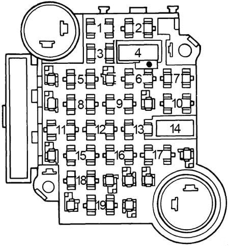
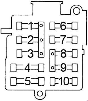
| Fuse | [A] | Protected Component |
| 1 | 5 | Instrument illumination and headlight warning |
| 2 | 20 | Electric choke (V6), closed loop |
| 3 | 5 | Instrument illumination and headlight warning |
| 4 | 30 | Circuit breaker: Power windows and roof |
| 5 | — | — |
| 6 | 25 | Heater, air conditioning, pulse wipers and deck lid |
| 7 | 10 | Electronic Control Module |
| 8 | — | — |
| 9 | 25 | Windshield wiper and washer |
| 10 | 20 | Hazard and stop lights |
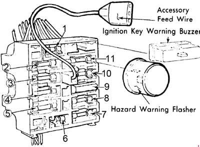
| 11 | 20 | Seat belt light and buzzer, heated back light relay, tailgate window release, map light and fuel economy light, cruise control, rear defogger blower, instrument gauges and indicator lights, electric choke |
| 12 | 20 | Tail, side marker, parking and license lights, clock radio |
| 13 | 10 | Radio |
| 14 | 30 | Circuit breaker: Power seats, door locks and heated back light |
| 15 | 20 | Turn signal and back-up lights |
| 16 | 20 | Clock, cigar lighter, glove box light, key buzzer, power antenna, clock radio, radio capacitor, dome and sail panel lights, trunk light, reading light, headlight on warning and door locks |
| 17 | — | — |
| 18 | — | — |
| 19 | 10 | Gauges, cruise control, torque converter clutch and indicator light |
| Circuit Breaker: Headlight Circuit — A thermo circuit breaker is incorporated in the headlight switch assembly to protect headlight circuits. Windshield Wiper — Integral with windshield wiper motor. | ||