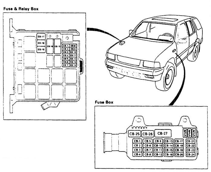
Isuzu Trooper (1997) – fuse box diagram
Year of production: 1997
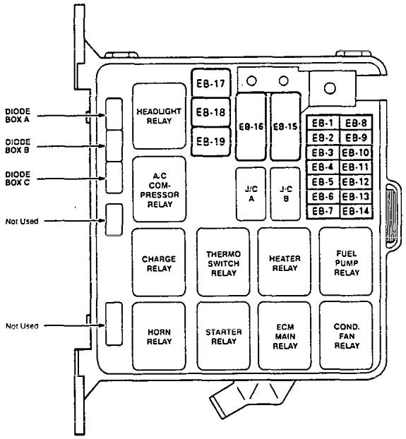
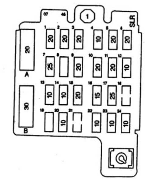
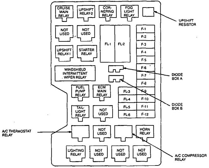
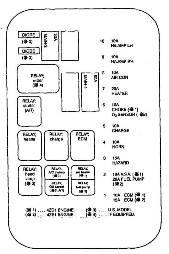
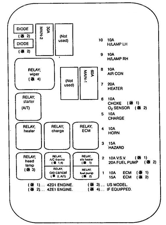
Engine compartment
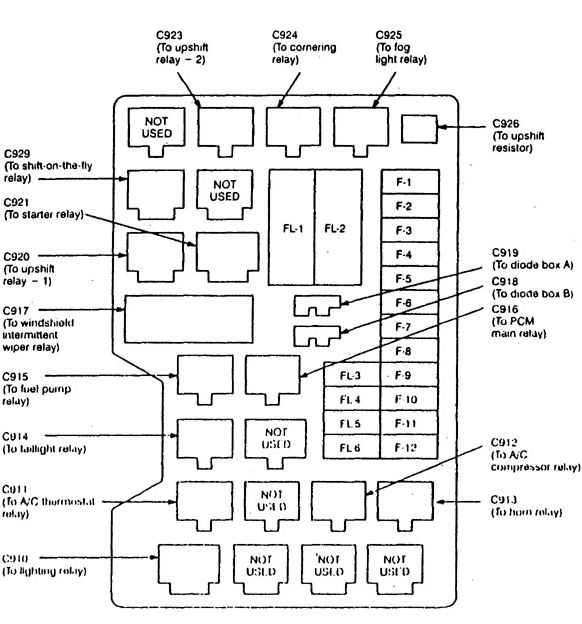
| Number | Fuse name | A | Function |
| F-1 | — | — | — |
| F-2 | 0 2 SENSOR HEATER | 10 | Engine control |
| F-3 | HORN HAZARD | 15 | Hams; Hazard light |
| F-4 | H/LAMP-LH | 15 | Headlights and fog lights |
| F-5 | H/LAMP-RH | 15 | Headlights |
| F-6 | — | — | — |
| F-7 | — | — | — |
| F-8 | (FRT FOG) | 15 | Fog lights |
| F-9 | ABS | 20 | Anti-lock brake system (ABS) |
| F-10 | FUEL PUMP | 15 | Fuel injection system |
| F-11 | — | — | — |
| F-12 | TAIL | 15 | Taillights |
| Fusible Link Number | Fusible Link Name | A | Circuit Protected |
| FL-1 | MAIN | 80 | See Power Distribution |
| FL-2 | KEY SW | 50 | See Power Distribution |
| FL-3 | ECM | 30 | Engine control |
| FL-4 | — | — | — |
| FL-5 | — | — | — |
| FL-6 | (ABS 4-WHEEL ONLY) | 40 | Anti·lock brake system, (ABS) |
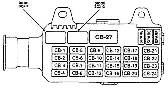
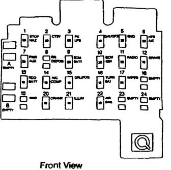
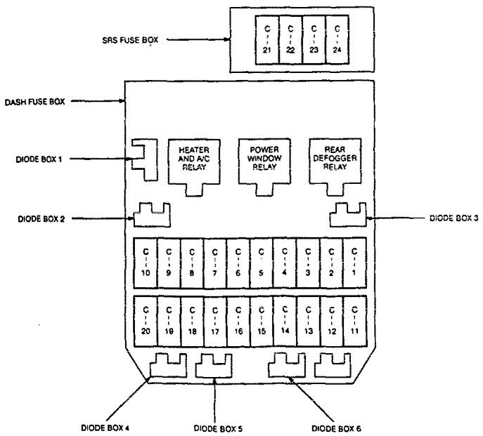
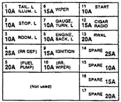
I/P Fuse panel

| Number | Fuse name | A | Function |
| C-1 | STARTER RELAY | 10 | Starting system |
| C-2 | (SEAT HEATER) | 15 | Heated seats |
| C-3 | TRUN BACK | 15 | Back up lights; Hazard warning lights, Cornering light, A/T gear position indicator |
| C-4 | ELEC. IGN. | 10 | Rear defogger; cruise control; power windows: Fuel injection system, Mirror defoggers, Interlock system, Power moonroof, Anti-lock brake system (ABS), Shift-on the fly |
| C-5 | FRT WIPER & WASHER | 15 | Windshield wiper/washer |
| C-6 | RR WIPER & WASHER | 10 | Rear wiper/washer |
| C-7 | (H/LAMP WIPER) | 10 | — |
| C-8 | ENGINE | 15 | Fuel injection system, Charging system |
| C-9 | IGN. COIL | 15 | Ignition system |
| C-10 | METER GAUGE | 10 | Gauges, Indicators, seat belt, Lights-on and ignition key reminder, Vehicle speed sensor (VSS) |
| C-11 | (AUDIO [ACC]) MIRROR | 10 | Sound system; power mirrors; clock |
| C-12 | CIGARETTE | 20 | Cigarette lighter |
| C-13 | (ANTI THEFT) | 10 | Security system |
| C-14 | STOP A/T CONT | 15 | Brake lights; automatic transmission control; Interlock system |
| C-15 | (AUDIO [B]) | 20 | Stereo sound system |
| C-16 | CLOCK [B} ROOM | 10 | Stereo sound system; Interior lights, Ignition key reminder, Securoty system, Power antenna, Clock |
| C-17 | RR DEFOG | 25 | Rear window defogger |
| C-18 | (DOOR LOCK) | 20 | Power door locks; Security system, Power windows |
| C-19 | BLOWER | 25 | Blower controls |
| C-20 | (AIR CON) | 10 | A/C compressor controls |
| C-21 | SRS-1 | 10 | Supplemental restraint system (SRS) |
| C-22 | SRS-2 | 10 | Supplemental restraint system (SRS) |
| C-23 | SRS-3 | — | — |
| C-24 | SRS-4 | — | — |
| Circuit Breaker Number | Circuit Breaker Name | A | Circuit Protected |
| C/B-1 | — | — | — |
| C/B-2 | (P/W, P/S, S/R) | 30 | Power windows: power sunroof; power seats; power door locks |
WARNING: Terminal and harness assignments for individual connectors will vary depending on vehicle equipment level, model, and market.