Isuzu Pickup (1993) – fuse box diagram
Year of production: 1993
Fuse box diagram
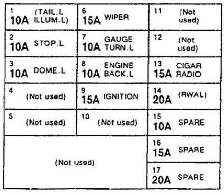
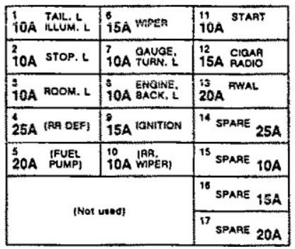
| Number | Function | A |
| 1 | Ex1enor lights: front park. rear side marker. park. and license lights; electronic engine control; dash and console lights | 10 |
| 2 | Brake lights | 10 |
| 3 | Dome and step lights | 10 |
| 4 | — | — |
| 5 | — | — |
| 6 | Wiper/washer | 15 |
| 7 | Indicators; gauges; turn and hazard lights | 10 |
| 8 | Charging system: back up lights; electronic engine control | 10 |
| 9 | Ignition system | 15 |
| 10 | — | — |
| 11 | — | — |
| 12 | — | — |
| 13 | Cigarette lighter: sound system | 15 |
| 14 | Rear wheel antilock brakes | 20 |
| 15 | Spare | 10 |
| 16 | Spare | 15 |
| 17 | Spare | 20 |
WARNING: Terminal and harness assignments for individual connectors will vary depending on vehicle equipment level, model, and market.