Chrysler Imperial (1981 – 1983) – fuse box diagram
Year of production: 1981, 1982, 1983
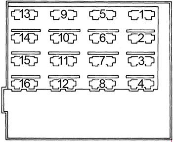
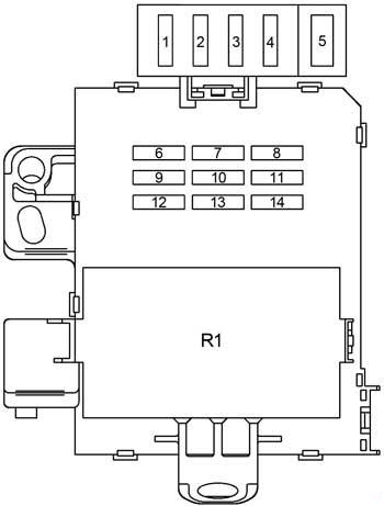
Fuse box

| № |
A |
Protected Component |
| 1 | 20 | Hazard flasher |
| 2 | 20 | In-tank fuel pump |
| 3 | 30 | Circuit Breaker: Power windows |
| 4 | 30 | Automatic temperature control blower motor, defogger relay, deck lid release, illuminated entry sense |
| 5 | 20 | Parking, tail, license, side marker, clock, instrument cluster and radio lights |
| 6 | 25 | Stop, door, map, reading, key cylinder, trunk, ignition switch, underhood, vanity and underpanel lights. Electric mirror motors, ignition switch time delay relay, chimes, radio memory, illuminated entry, electronic cluster memory, security alarm and seat switch |
| 7 | 25 | Horn, horn relay, cigar lighter, power antenna and glove box light |
| 8 | 30 | Circuit Breaker: Power door locks and seats |
| 9 | – | – |
| 10 | – | – |
| 11 | 5 | Brake warning, seat belt warning and low fuel sensor, oil pressure, door ajar and temperature indicators, speed control, cluster electronics, charge light, low voltage light and chimes |
| 12 | 20 | Heated side mirror, air conditioning radiator fan motor |
| 13 | 4 | Cluster, title and radio illumination and radio display dimming |
| 14 | 20 | Radio power booster |
| 15 | 5 | Radio, power antenna controller |
| 16 | 20 | Back-up and turn signal lights, air conditioning clutch and idle stop solenoid, cornering lights |
WARNING: Terminal and harness assignments for individual connectors will vary depending on vehicle equipment level, model, and market.