Ford Thunderbird (1983 – 1988) – fuse box diagram
Year of production: 1983, 1984, 1985, 1986, 1987, 1988
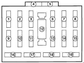
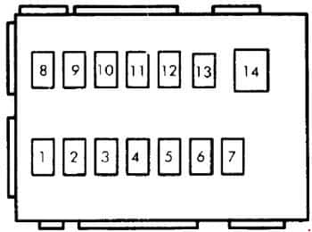
Fuse box
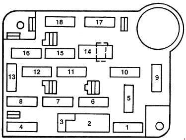
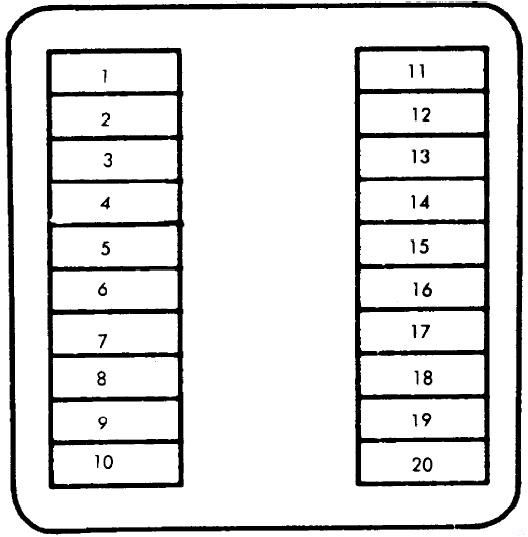
| No. | A | Description |
| 1 | 15 | Brake & Hazard Warning Lights, Speed Control Module, Cornering Light Relay |
| 2 | 6 | Circuit Breaker: Windshield Wiper & Washer Pump, Interval Wiper |
| 3 | – | – |
| 4 | 15 | Taillights, License & Parking Lights, Side Marker & Coach Lights, Cluster Illumination Lights, Radio & Clock Illuminator, A/C-Heater Illumination |
| 5 | 15 | Turn Signal & Back-Up Lights, Keyless Entry Illumination, Day/Night Mirror, Turbo Overboost Buzzer |
| 6 | 20 | Heated Back Light Control, Deck Lid Release, Electronic Chime Module, Lights Outage & Clock Display, Cornering & Rear Reading Lights, Tripminder, Illuminated Entry, Anti-Theft Module, Radio & Cluster Illumination |
| 7 | 15 | Foglights (Turbo Only) |
| 8 | 15 | Courtesy & Glove Box Lights, Key Warning Buzzer, Illuminated Entry Module, Remote Electric Mirrors, Electronic Radio & Cluster Memories, Anti-Theft Relay & Clock |
| 9 | 30 | A/C-Heater Blower Motor |
| 10 | 20 | Horn, Cigarette Lighter, Flash-To-Pass Feature, Fuel Filler Door, Speed Control |
| 11 | 20 | Radio, Power Antenna, Sound Amplifier |
| 12 | 20 | Circuit Breaker: Power Seat & Door Locks, Keyless Entry, Fuel Filler Door Lock |
| 13 | 5 | Instrument Cluster, Radio, Climate Control, Instrument Panel Illumination |
| 14 | 20 | Power Windows, Power Moon Roof |
| 15 | 10 | Taillights, Parking Lights, License & Coach Lights |
| 16 | 4 | EATC Memory, Horn, Cigarette Lighter |
| 17 | 15 | Electronic Cluster Tripminder, Fuel Gauge, A/C Clutch, Speed Control Module, Graphic Warning Module |
| 18 | 10 | Warning Indicator Lights, Auto Light System, Electronic |
WARNING: Terminal and harness assignments for individual connectors will vary depending on vehicle equipment level, model, and market.