Pontiac Sunbird (1979) – fuse box diagram
Year of production: 1979
Fuse Box
| No. |
A |
Circuit Protected |
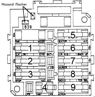
| 1 | 10 | Electric fuel pump |
| 2 | 20 | Cigar lighter and clock feed, glove box and dome light, air conditioning anti-dieseling relay, key warning buzzer |
| 3 | 20 | License, tail front park and side marker lights |
| 4 | 20 | Stop and hazard warning lights |
| 5 | 4 | Instrument panel illumination, shift indicator and radio lights |
| 6 | 25 | Heater and A/C blower motor |
| 7 | 20 | Directional signals and back-up lights |
| 8 | 20 | Low coolant fuel gauge, brake warning, seat belt warning, heated rear glass, seat belt timer and buzzer, tachometer voltmeter, generator and temperature pressure telltale lights, controlled cycle wipers and electronic fuel control system |
| 9 | 10 | Radio, defogger |
| 10 | 25 | Windshield wiper and washer |
WARNING: Terminal and harness assignments for individual connectors will vary depending on vehicle equipment level, model, and market.