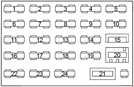
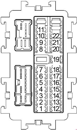
No.
|
A
|
Circuit Protected |
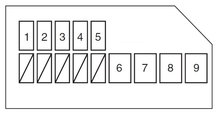
| 1 |
– |
– |
| 2 |
– |
– |
| 3 |
– |
– |
| 4 |
– |
– |
| 5 |
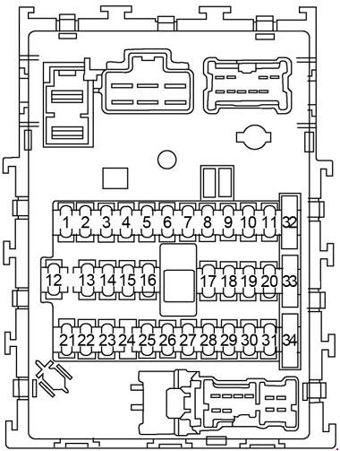
10 |
Door Mirror, Warning Lamps, Warning Chime, CVT Indicator Lamp |
| 6 |
10 |
Combination Meter, Remote Keyless Entry System, Headlamp, Turn Signal and Hazard Warning Lamps, Front Fog Lamp, Parking Lamp, License Lamp, Tail Lamp, Combination Switch, Illumination, Audio, Daytime Light System, Hands Free Telephone, Vehicle Security (Theft Warning) System, Power Window, Audio Visual Communication System, Vehicle Information and Integrated Switch System, Intelligent Key System, Room/Map Lamps, Vanity Lamp, Luggage Lamp |
| 7 |
15 |
Power Socket |
| 8 |
10 |
Rear Window Defogger |
| 9 |
10 |
Warning Chime, Room/Map Lamps, Vanity Lamp, Luggage Lamp, Power Door Lock, Intelligent Key System, Trunk Lid Opener |
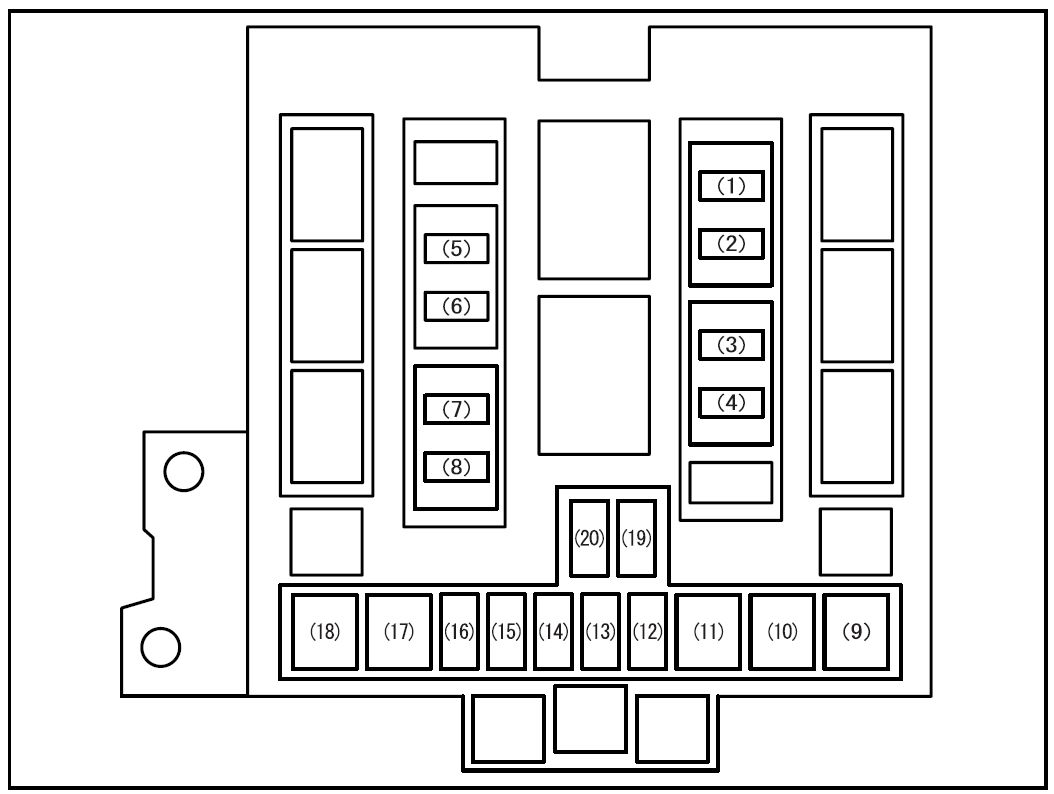
| 10 |
15 |
Heater System, Manual Air Conditioner |
| 11 |
15 |
Heater System, Manual Air Conditioner |
| 12 |
10 |
Illumination, Malfunction Indicator Lamp, CVT Shift Lock System, Electronic Controlled Power Steering, Intelligent Key System, Headlamp, Turn Signal and Hazard Warning Lamps, Low Tire Pressure Warning System, Warning Chime, Daytime Light System, Hands Free Telephone, Vehicle Security (Theft Warning) System, Remote Keyless Entry System, Nissan Anti-Theft System, Front Wiper and Washer, Front Fog Lamp, Sunroof, Combination Switch, Heater System, Manual Air Conditioner, Parking Lamp, License Lamp, Tail Lamp, Room/Map Lamps, Vanity Lamp, Luggage Lamp, Vehicle Information and Integrated Switch System, Power Window, Rear Window Defogger, Audio Visual Communication System, ASCD Brake Switch, Park/Neutral Position Switch, CVT Indicator Lamp, Starting System, Heated Seat |
| 13 |
10 |
Supplemental Restraint System |
| 14 |
10 |
Back-up Lamp, Combination Meter, Intelligent Key System, Headlamp, Turn Signal and Hazard Warning Lamps, Illumination, Warning Chime, Daytime Light System, Low Tire Pressure Warning System, Electronic Controlled Power Steering, Charging System, Warning Lamps, Park/Neutral Position Switch, ASCD Indicator, CVT Indicator Lamp, Malfunction Indicator Lamp, Anti-lock Brake System, Overdrive Control Switch, Supplemental Restraint System, Audio Visual Communication System |
| 15 |
10 |
Front Wiper and Washer |
| 16 |
15 |
QR: Air Fuel Ratio Sensor, Fuel Ignition System Function, Heated Oxygen Sensor |
| 17 |
20 |
Audio |
| 18 |
15 |
Power Socket |
| 19 |
10 |
Stop Lamp, Combination Meter, Illumination, Power Door Lock, Brake Switch, Daytime Light System, Intelligent Key System, Headlamp, Nissan Anti-Theft System, Turn Signal and Hazard Warning Lamps, Vehicle Security (Theft Warning) System, Electronic Controlled Power Steering, Warning Chime, Low Tire Pressure Warning System, CVT Indicator Lamp, Heater, Manual Air Conditioner, Warning Lamps, Anti-lock Brake System, ASCD Indicator, Room/Map Lamps, Vanity Lamp, Luggage Lamp, Audio Visual Communication System, Malfunction Indicator Lamp, Rear Window Defogger, ASCD Brake Switch |
| 20 |
10 |
Intelligent Key System, Audio Visual Communication System, Vehicle Information and Integrated Switch System, Power Door Lock, Remote Keyless Entry System, Nissan Anti-Theft System, Trunk Lid Opener, Vehicle Security (Theft Warning) System, Warning Chime, Combination Switch, Daytime Light System, Front Fog Lamp, Headlamp, Room/Map Lamps, Vanity Lamp, Luggage Lamp, Illumination, Turn Signal and Hazard Warning Lamps, Parking Lamp, License Lamp, Tail Lamp, ASCD Brake Switch |
| 21 |
10 |
Power Door Lock, Warning Chime, Intelligent Key System, Remote Keyless Entry System, Room/Map Lamps, Vanity Lamp, Luggage Lamp |
| 22 |
10 |
Hands Free Telephone |