Dacia 1307 – fuse box diagram
Year of production:
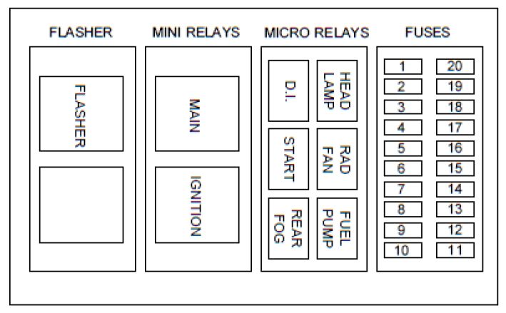
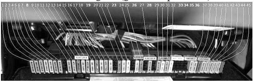
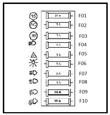
Fuses
| № | A | Component |
|---|---|---|
| F01 | 15 | Rear lights and board panel supply, STOP lights; |
| F02 | 15 | 4×4 electro-vacuum control*, climate control with CA*, speed over-limit 120 km/h indicator relay*, vehicle speed transducer*; |
| F03 | 15 | GMV climate control, clock; |
| F04 | 15 | Fog lights, ceiling light, ashtray, windscreen wiper – cleaner |
| F05 | 8 | Direction and break-down signalization |
| F06 | 8 | Position lights, lighting of the board panel,ashtray, lighter, gloves box, clock, switches; |
| F07 | 8 | Left driving lights; |
| F08 | 8 | Right driving lights; |
| F09 | 10 | Left high beam; |
| F10 | 10 | Right high beam. |
| * for vehicle with 4×4, CA or speed over-limit indicator. | ||
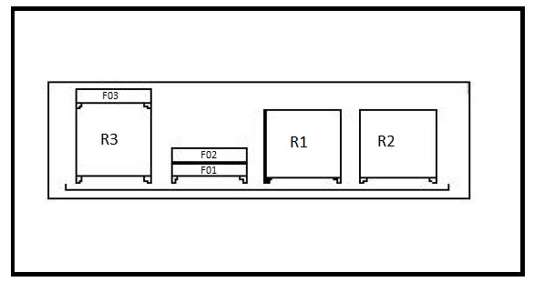
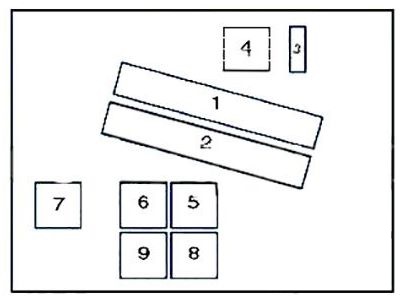
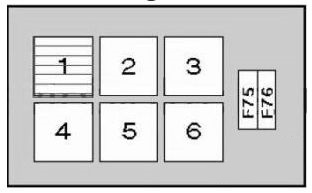
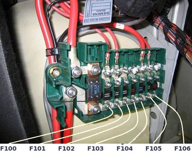
Electric circuits protected by fuses and relays

| № | A | Component |
| F01 | 10 | Fuel electric pump |
| F02 | 10 | Oxygen rod |
| F03 | 15 | Fog lights |
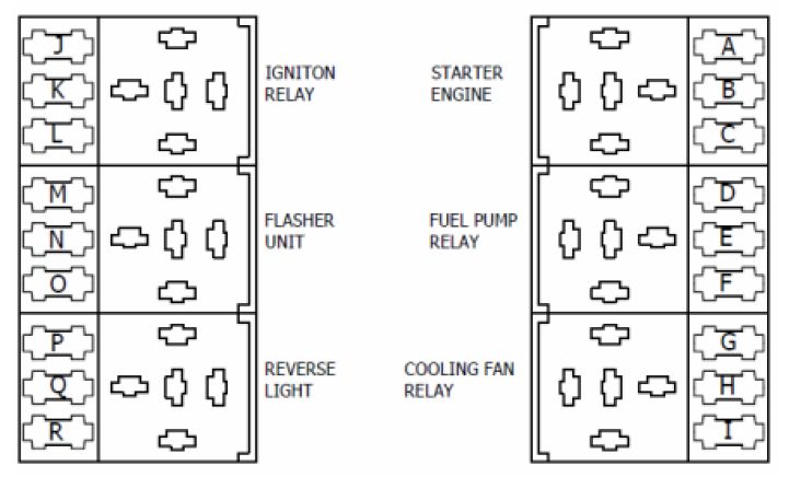
| Relay | Component |
| R1 | Oxygen rod, fuel electric pump. |
| R2 | Injection computer, injection witness. |
| R3* | Fog lights |
| * -for vehicle with fog lights | |
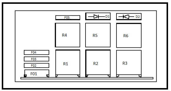
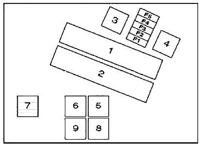
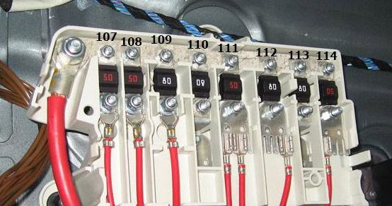
The vehicles provided with AC system, the fuse box situated in the engine compartment is fixed on the left mudguard coating, having the following configuration.

| № | A | Component |
| F01 | 10 | A.C. compressor |
| F02 | 10 | Oxygen rod |
| F03 | 10 | Fuel electric pump |
| F04 | 30 | G.M.V. cooling |
| F05* | 15 | Fog lights |
| * -for vehicle with fog lights | ||
| Diode | Type | Component |
| D1 | 6 | A.C. compressor |
| D2 | 6 | A.C.pressure gauge anti-return |
| Relay | Component |
| R1 | Oxygen rod, fuel electric pump |
| R2 | A.C. compressor |
| R3 | Injection computer, injection witness. |
| R4* | Fog lights. |
| R5 | G.M.V. cooling |
| R6 | Injection computer ( thermo-protection A.C.) |
| * -for vehicle with fog lights | |
WARNING: Terminal and harness assignments for individual connectors will vary depending on vehicle equipment level, model, and market.