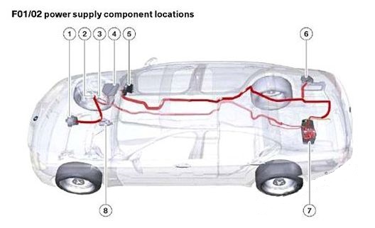
BMW 5-Series (F10/F11/F07/F18; 2011 – 2017) – fuse box diagram
Year of production: 2011, 2012, 2013, 2014, 2015, 2016, 2017
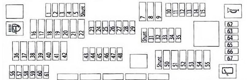
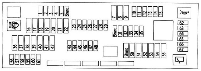
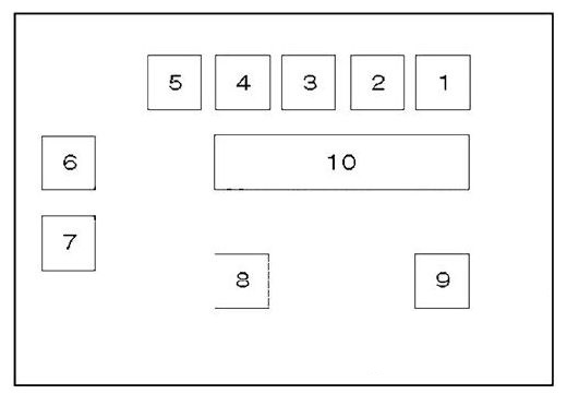
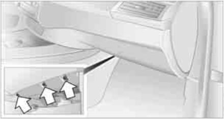
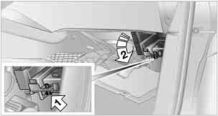
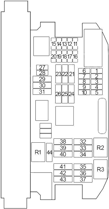
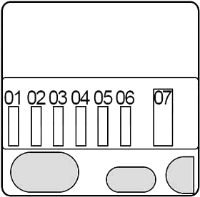
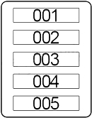
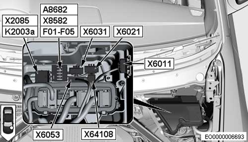
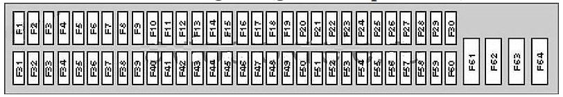
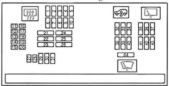
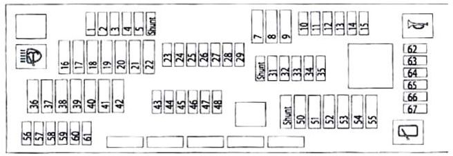
Fuse box in the glove compartment
| No | A |
|---|---|
| 1 | 10 |
| 2 | 5 |
| 3 | 5 |
| 4 | 5 |
| 5 | 10 |
| 7 | 30 |
| 8 | 30 |
| 9 | 30 |
| 10 | 10 |
| 11 | 7,5 |
| 12 | 5 |
| 13 | 5 |
| 14 | 15 |
| 15 | 20 |
| 16 | 40 |
| 17 | 30 |
| 18 | 30 |
| 19 | 20 |
| 20 | 20 |
| 21 | 30 |
| 22 | 30 |
| 23 | 5 |
| 24 | 10 |
| 25 | 5 |
| 26 | 5 |
| 27 | 5 |
| 28 | — |
| 29 | — |
| 31 | 5 |
| 32 | 7,5 |
| 33 | 5 |
| 34 | 5 |
| 35 | 10 |
| 36 | 30 |
| 37 | 30 |
| 38 | 40 |
| 39 | 40 |
| 40 | 30 |
| 41 | — |
| 42 | 30 |
| 43 | 5 |
| 44 | 5 |
| 46 | 5 |
| 47 | 20 |
| 48 | 5 |
| 50 | 40 |
| 51 | 30 |
| 52 | 30 |
| 53 | 30 |
| 54 | 20 |
| 55 | 20 |
| 56 | 5 |
| 57 | — |
| 58 | 5 |
| 59 | 10 |
| 60 | 5 |
| 61 | 20 |
| 62 | 15 |
| 63 | 10 |
| 64 | 7,5 |
| 65 | 15 |
| 66 | 7,5 |
| 67 | 10 |
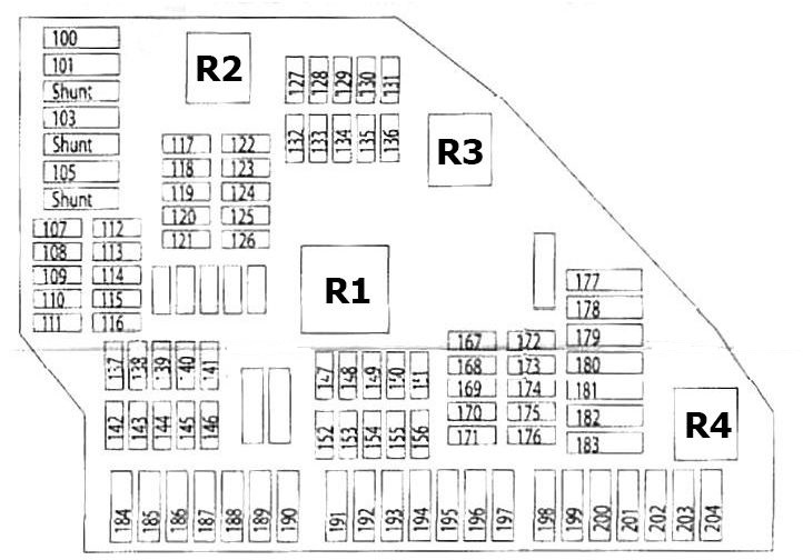
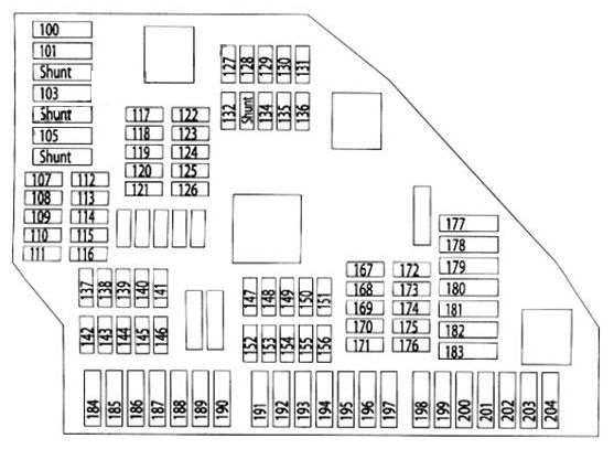
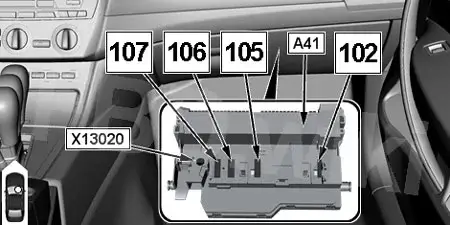
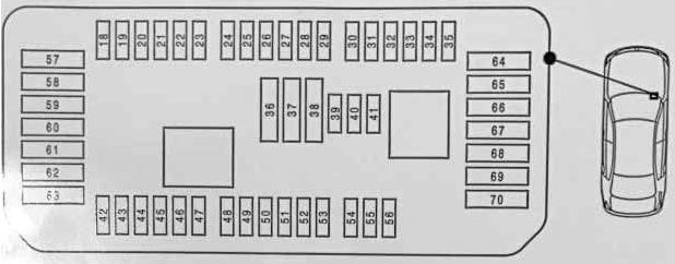
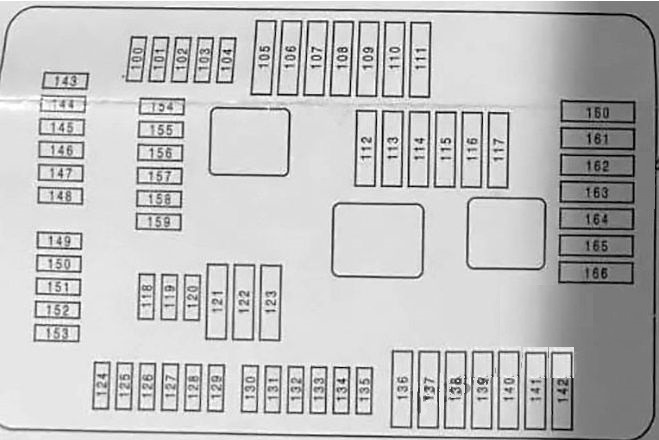
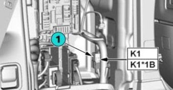
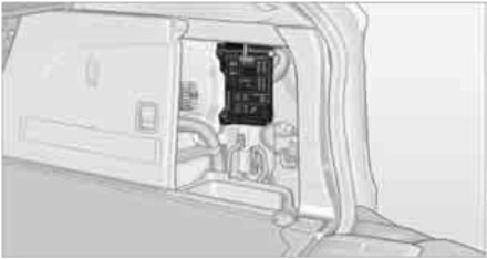
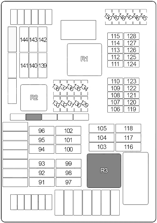
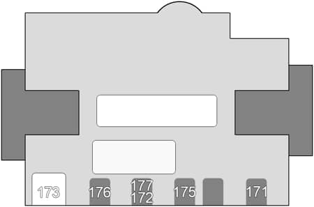
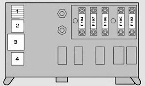
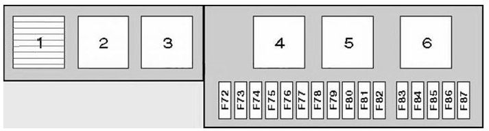
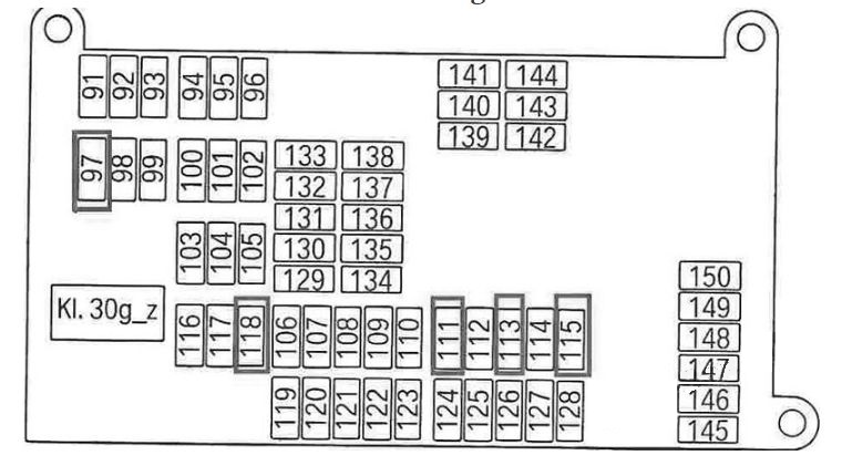
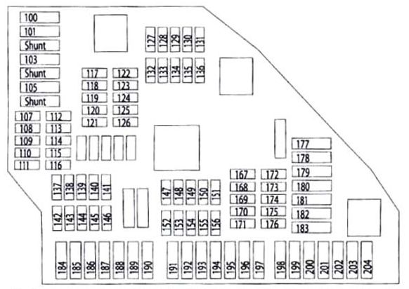
Fuse box in the luggage compartment
It is located on the right side, behind the cover.
| № | A |
|---|---|
| 100 | 20 |
| 101 | 40 |
| 103 | 20 |
| 105 | — |
| 107 | 5 |
| 108 | 5 |
| 109 | 10 |
| 110 | 10 |
| 111 | 20 |
| 112 | 5 |
| 113 | 5 |
| 114 | 5 |
| 115 | — |
| 116 | 7,5 |
| 117 | 5 |
| 118 | 10 |
| 119 | 15 |
| 120 | 5 |
| 121 | 5 |
| 122 | — |
| 123 | 5 |
| 124 | 5 |
| 125 | 5 |
| 126 | — |
| 127 | — |
| 128 | 10 |
| 129 | — |
| 130 | — |
| 131 | 5 |
| 132 | 5 |
| 133 | — |
| 134 | 5 |
| 135 | 5 |
| 136 | 5 |
| 137 | 5 |
| 138 | 5 |
| 139 | 5 |
| 140 | — |
| 141 | — |
| 142 | 20 |
| 143 | 10 |
| 144 | 10 |
| 145 | 20 |
| 146 | — |
| 147 | 15 |
| 148 | 20 |
| 149 | 10 |
| 150 | — |
| 151 | 10 |
| 152 | 5 |
| 153 | 5 |
| 154 | 5 |
| 155 | 15 |
| 156 | 5 |
| 167 | — |
| 169 | 5 |
| 170 | — |
| 171 | — |
| 172 | — |
| 173 | — |
| 174 | — |
| 175 | 10 |
| 176 | 15 |
| 177 | 20 |
| 178 | 30 |
| 179 | 30 |
| 180 | 30 |
| 181 | — |
| 182 | 40 |
| 183 | 40 |
| 184 | 20 |
| 185 | 30 |
| 186 | 40 |
| 187 | 30 |
| 188 | 30 |
| 189 | — |
| 190 | 30 |
| 191 | 30 |
| 192 | — |
| 193 | — |
| 194 | — |
| 195 | 30 |
| 196 | — |
| 197 | 30 |
| 198 | 30 |
| 199 | 30 |
| 200 | 40 |
| 201 | — |
| 202 | 30 |
| 203 | 30 |
| 204 | 30 |
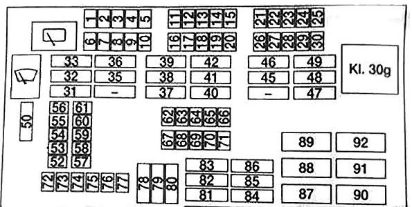
Assignment of the fuses
| Symbol | Number |
| 2, 36, 40, 43, 50, 178, 180 | |
| 1, 8, 13, 24, 39, 43, 45, 134 | |
| 19, 100, 145, 148 | |
| 4, 8, 10, 13, 24, 25, 31, 44, 113, 116, 118, 119, 120, 121, 123, 124, 125, 131, 200 | |
| 8, 32 | |
| 34, 37, 45, 107, 118 | |
| 63, 64, 138, 178 | |
| 33, 38, 56, 103, 136, 186 | |
| 8, 13, 16, 66, 101, 154 | |
| 12, 13, 16, 66, 154 | |
| 58, 60, 135, 169 | |
| 8, 134 | |
| 43, 46, 121, 137 | |
| 8, 62 | |
| 60, 167, 179, 180 | |
| 2, 8, 14, 15, 32, 38, 56, 58, 110, 143, 144, 149, 152 | |
| 7, 8, 9, 17, 18, 32 | |
| 31, 187, 188, 190, 191 | |
| 27, 32, 52, 53, 57, 112, 114 | |
| 33, 198, 199 | |
| OBD | 3 |
| 121, 177 | |
| 46 | |
| 8, 51, 55 | |
| 203, 204 | |
| 8 | |
| 5, 13, 16, 48, 66 | |
| 34, 37, 45, 131, 134 | |
| 5, 8, 10, 13 | |
| 8, 11, 31, 44, 128, 156 | |
| 44, 48, 142, 195, 202 | |
| 33, 35, 184 | |
| 135, 139, 184 | |
 |
20, 21, 22, 35, 39, 42, 47, 48, 59, 107, 128, 135, 137, 138, 175 |
| 152, 182 | |
| 139 | |
| 8, 36 | |
| 8, 36 | |
| 153, 155, 183 | |
| 58, 61 | |
| 23, 27, 117 | |
| 61, 100, 109, 114, 151 | |
| 11, 58, 61, 185 | |
| 54, 65, 108, 147, 175 |
WARNING: Terminal and harness assignments for individual connectors will vary depending on vehicle equipment level, model, and market.