Mercury Milan Hybrid (2010 – 2011) – fuse box diagram
Year of production: 2010, 2011
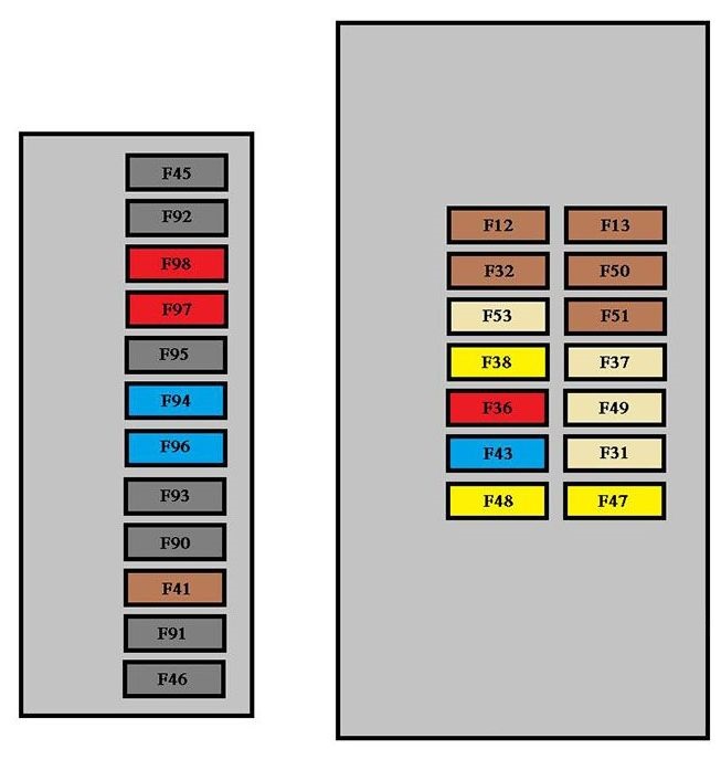
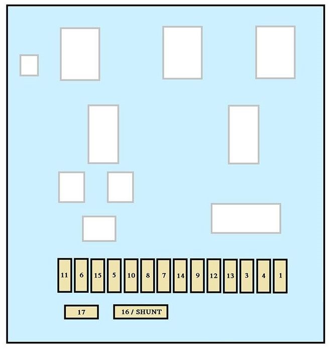
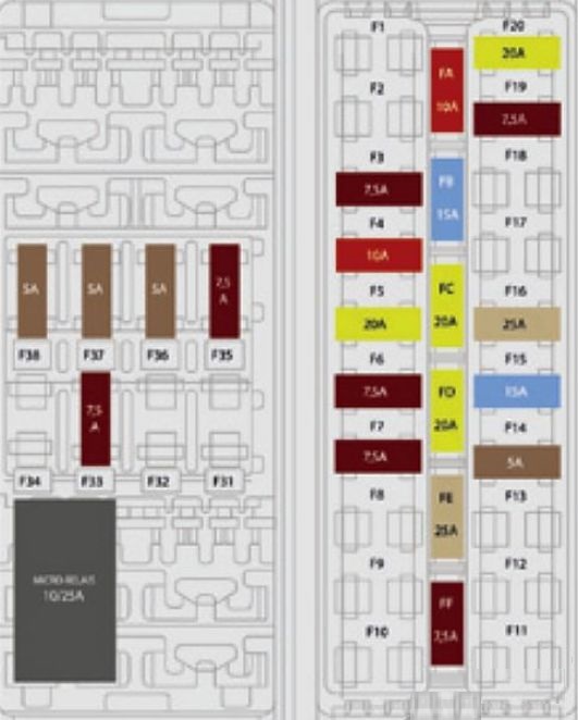
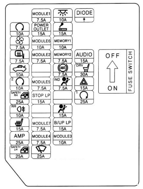
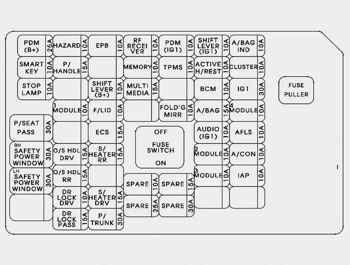
Passenger compartment fuse panel
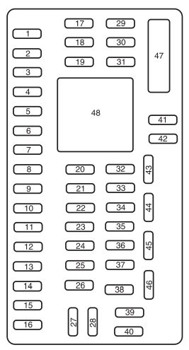
The fuse panel is located below and to the left of the steering wheel by the brake pedal. Remove the panel cover to access the fuses.
| No. | A | Circuits protected |
| 1 | 30 | Driver smart window motor |
| 2 | 15 | Brake on/off switch, Center high-mount stop lamp |
| 3 | 15 | Hybrid: HEV battery fan |
| 4 | 30 | Hybrid: 110V Inverter |
| 5 | 10 | Keypad illumination, Brake shift interlock |
| 6 | 20 | Turn signal lamps |
| 7 | 10 | Low beam headlamps (left) |
| 8 | 10 | Low beam headlamps (right) |
| 9 | 15 | Courtesy lights |
| 10 | 15 | Backlighting, Puddle lamps |
| 11 | 10 | AWD module |
| 12 | 7.5 | Power outside mirrors |
| 13 | 5 | SYNC® module |
| 14 | 10 | Electronic finish panel (EFP) radio and climate control buttons module. Navigation display, Center information display, GPS module |
| 15 | 10 | Climate control |
| 16 | 15 | Not used (spare) |
| 17 | 20 | Door locks, Trunk release |
| 18 | 20 | Heated seats |
| 19 | 25 | Amplifier |
| 20 | 15 | On-board diagnostic connector |
| 21 | 15 | Fog lamps |
| 22 | 15 | Front sidemarker lamps, Park lamps, License plate lamp |
| 23 | 15 | High beam headlamps |
| 24 | 20 | Horn |
| 25 | 10 | Demand lamps/power saver relay |
| 26 | 10 | Instrument cluster battery power |
| 27 | 20 | Ignition switch |
| 28 | 5 | Radio crank sense circuit |
| 29 | 5 | Instrument cluster ignition power |
| 30 | 5 | Not used (spare) |
| 31 | 10 | Not used (spare) |
| 32 | 10 | Restraint control module |
| 33 | 10 | Not used (spare) |
| 34 | 5 | Not used (spare) |
| 35 | 10 | Reverse sensing system, Blind spot information system, Heated seats, Rearview camera, 110V inverter, AWD |
| 36 | 5 | Passive Anti-Theft Sensor (PATS) transceiver |
| 37 | 10 | Hybrid: Humidity sensor |
| 38 | 20 | Subwoofer amplifier |
| 39 | 20 | Radio |
| 40 | 20 | Not used (spare) |
| 41 | 15 | Automatic dimming mirror, Moon roof, Compass, Ambient lighting |
| 42 | 10 | Electronic stability control, Electronic power assist steering |
| 43 | 10 | Rain Sensor |
| 44 | 10 | Fuel diode/Powertrain control module |
| 45 | 5 | Heated backlight and blower relay coil, Wiper washer |
| 46 | 7.5 | Occupant classification sensor (OCS) module, Passenger airbag off lamp |
| 47 | 30 | Circuit Breaker:Power windows |
| Relay | ||
| 48 | Delayed accessory | |
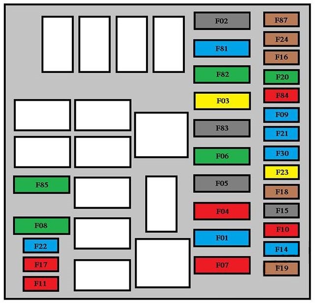
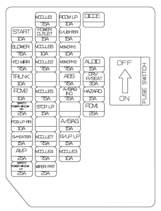
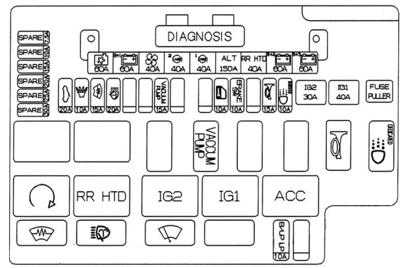
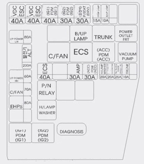
Engine Compartment Fuse Box
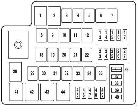
| No. | A | Circuits protected |
| 1 | 50 | Electronic power assist steering B+ |
| 2 | 50 | Electronic power assist steering B+ |
| 3 | 40 | Powertrain control module (aux relay 5 power) |
| 4 | — | Not used |
| 5 | — | Not used |
| 6 | 40 | Rear defrost (aux relay 4 power) |
| 7 | 40 | Vacuum pump (aux relay 6 power) |
| 8 | 50 | Brake system controller pump |
| 9 | 20 | Wiper washer |
| 10 | 30 | Brake system controller valves |
| 11 | — | Not used |
| 12 | — | Not used |
| 13 | 15 | Motor electronics coolant/heater pump (relay 42 & 44 power) |
| 14 | — | Not used |
| 15 | — | Not used |
| 16 | — | Not used |
| 17 | 10 | HEV high voltage battery module |
| 18 | 30 | ’11: 110V electrical outlet |
| 19 | — | Not used |
| 20 | — | Not used |
| 21 | — | Not used |
| 22 | 20 | Console power point |
| 23 | 10 | Powertrain control module/ Transmission control module keep-alive power, Canister vent |
| 24 | — | Not used |
| 25 | — | Not used |
| 26 | 15 | Left headlamp (aux relay 1 power) |
| 27 | 15 | Right headlamp (aux relay 2 power) |
| 28 | 60 | Cooling fan motor |
| 29 | 20 | Front power point |
| 30 | 30 | Fuel relay (relay 43 power) |
| 31 | 30 | Passenger power seat |
| 32 | 30 | Driver power seat |
| 33 | 20 | Moon roof |
| 34 | — | Not used |
| 35 | 40 | Front A/C blower motor (aux relay 3 power) |
| 36 | 1 | Diode: Fuel pump |
| 37 | 5 | Vacuum pump monitoring |
| 38 | 10 | Heated side mirrors |
| 39 | 10 | Transmission control module |
| 40 | 10 | Powertrain control module |
| 45 | 15 | Injectors |
| 46 | 15 | Coil on plugs |
| 47 | 10 | Powertrain control module (general): Heater pump, Motor electronics coolant pump relay coils, DC/DC converter, Back-up lamps, Brake controller |
| 48 | 20 | HEV high voltage battery module, Fuel pump relay |
| 49 | 15 | Powertrain control module (emissions related) |
| Relay | ||
| 41 | Backup lamps | |
| 42 | Heater pump | |
| 43 | Fuel pump | |
| 44 | Motor electronics coolant pump | |
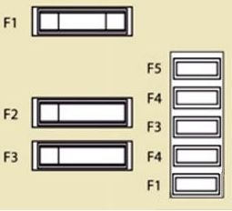
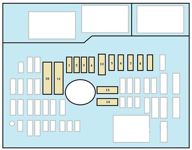
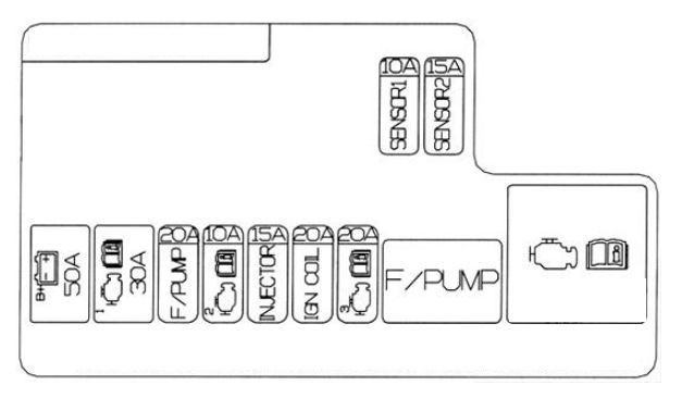
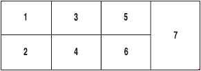
Auxiliary relay box (only Hybrid)
The auxiliary relay box is located in front of the radiator in the engine compartment.
| No. | Circuits protected |
| 1 | Left headlamp |
| 2 | Right headlamp |
| 3 | Blower motor |
| 4 | Rear window defogger |
| 5 | Powertrain control module |
| 6 | Vacuum pump cut-off |
| 7 | Vacuum pump |
WARNING: Terminal and harness assignments for individual connectors will vary depending on vehicle equipment level, model, and market.