Cadillac Catera (1997 – 2001) – fuse box diagram
Year of production: 1997, 1998, 1999, 2000, 2001
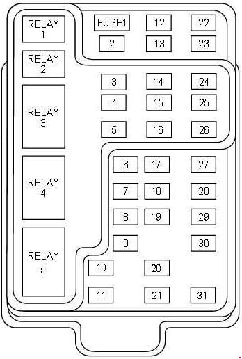
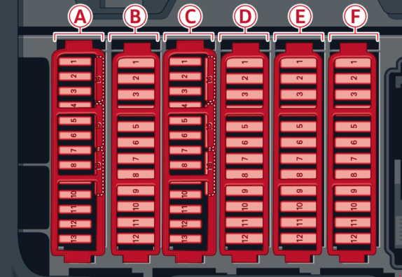
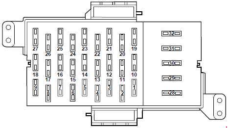
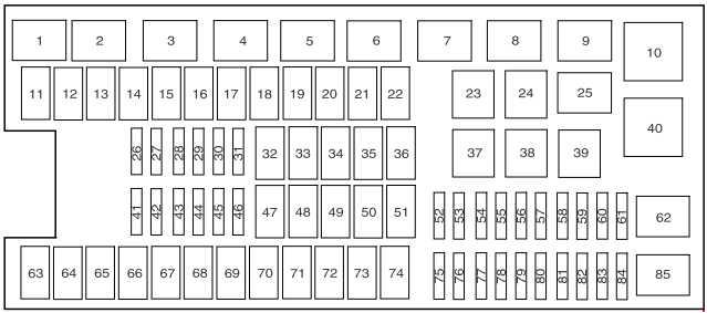
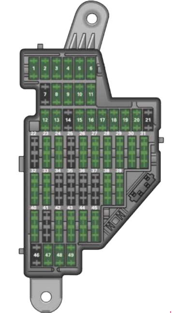
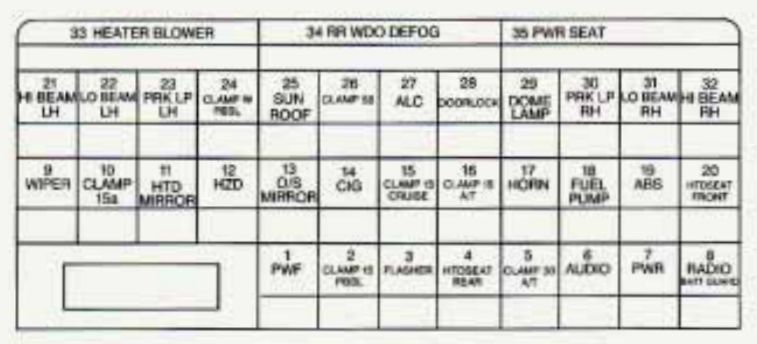
Instrument Panel Fuse Block (Driver’s Side)
The fuse block is located below the steering wheel on the driver’s side.
| № |
Usage |
| 1 | RH and LH Front Side Door Window Regulator Motor, LH Front Side Door Window Switch |
| 2 | Stoplamp Switch, Cruise Control Release Switch |
| 3 | Automatic Transmission Range Switch, Automatic Transmission Control Indicator, Power Steering Control Module, Hazard Warning Switch, Automatic Transmission Winter Mode Switch, Transmission Control Module (TCM) |
| 4 | RH and LH Rear Seat Cushion Heater Relay, Rear Sunshade Motor, Accessory Power Outlet |
| 5 | Transmission Control Module |
| 6 | Radio Speaker Amplifier |
| 7 | RH and LH Rear Side Door Window Regulator Motor |
| 8 | Headlamp Switch, Turn Signal Switch, Horn Relay, CD Changer, Multifunction Relay |
| 9 | Windshield Wiper Motor and Relay, Windshield Wiper and Windshield Washer Switch |
| 10 | Body Control Module (BCM), Heater Water Auxiliary Pump, Fan Control Relays, Auxiliary Water Pump Relay |
| 11 | Heater and A/C Control, RH and LH Outside Rearview Mirrors |
| 12 | Hazard Warning Switch, Instrument Cluster, Data Link Connector (DLC), Stoplamp Switch, Gage Cluster, Heater and A/C Control. |
| 13 | Remote Control Outside Rearview Mirror Switch, A/C Compressor Relay, Coolant Fan Test Connector, A/C Load Switch |
| 14 | Cellular Telephone, RH and LH Windshield Washer Nozzles, Driver and Passenger Heated Seat Switch, Heater and A/C Control, Heated Outside Rearview Mirror and Rear Window Defogger Relay |
| 15 | Rear Suspension Leveling Air Compressor Relay, Instrument Cluster, Gage Cluster, Cruise Control Switch, Headlamp Switch, Multifunction Relay, Passenger and Driver Heated Seat Relay, BCM, Sunroof Actuator, Automatic Level Control Sensor, RH and LH Heated Rear Seat Switch, RH and LH Heated Rear Seat Cushion Relay, Driver Seat Adjuster Memory Module, LH Front Side Door Window Switch, Inside Rearview Mirror |
| 16 | Cigarette Lighter (Front and Console) |
| 17 | Horn #1 and #2 |
| 18 | Fuel Pump |
| 19 | Electronic Brake/Traction Control Module |
| 20 | Passenger and Driver Heated Seat Relay |
| 21 | Daytime Running Lamp (DRL) Relay, LH High – Beam Headlamp Relay |
| 22 | Headlamp Switch, LH Low – Beam Headlamp |
| 23 | LH Parking Lamp and Turn Signal Lamps, LH Rear Sidemarker Lamp, Multifunction Relay, LH Stoplamp and Taillamp |
| 24 | Lifting Magnet, BCM, Gage Cluster |
| 25 | Sunroof Actuator |
| 26 | Headlamp Switch, RH and LH Front Sidemarker Lamp, Middle Taillamp, RH and LH Rear License Plate Lamp, Radio, Automatic Transmission Control Indicator, Heater and A/C Control |
| 27 | Automatic Level Control Sensor, Rear Suspension Leveling Air Compressor and Relay |
| 28 | Door Lock Relay |
| 29 | Multifunction Relay, OnStar System |
| 30 | RH Parking Lamp and Turn Signal Lamp, RH Rear Sidemarker Lamp, RH Stoplamp and Taillamp |
| 31 | RH Low – Beam Headlamp Turn Signal Switch |
| 32 | RH High – Beam Headlamp Relay |
| 33 | Blower Controller, A/C Compressor Relay |
| 34 | Heated Rear Window Defogger Relay |
| 35 | Passenger Seat Adjuster Switch, Driver Seat Adjuster Memory Module |
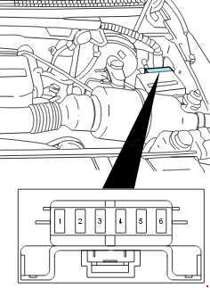
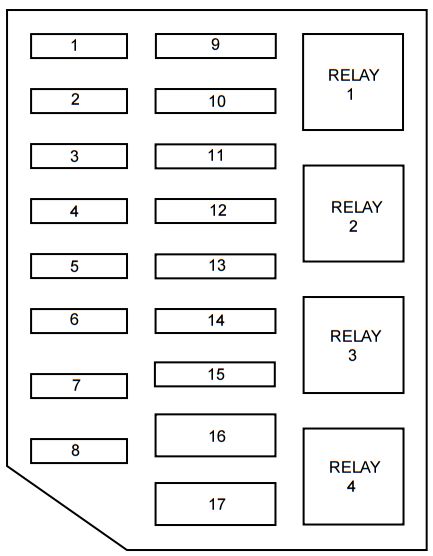
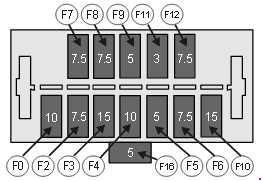
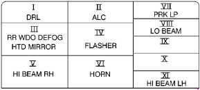
Relay Box
The relay box is located on the lower part of the instrument panel, to the right of the steering column.
| № | Usage |
| I | Daytime Running Lamps |
| II | Automatic Level Control |
| III | Rear Window Defogger, Heated Mirrors |
| IV | Hazard Warning Flashers |
| V | High – Beam Headlamps II (RH) |
| VI | Horn |
| VII | Parking Lamps and Turn Signal Lamps |
| VIII | Low – Beam Headlamps |
| IX | Not Used |
| X | Not Used |
| XI | High – Beam Headlamps I (LH) |
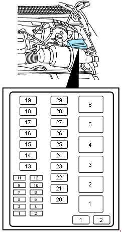
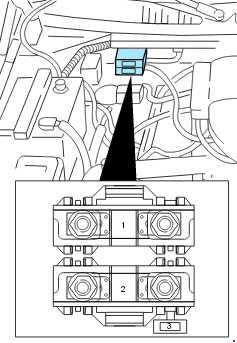
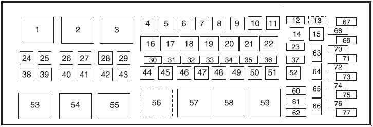
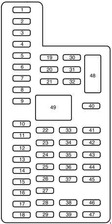
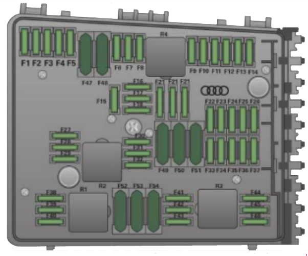
Engine Compartment Relay Center
The relay center is located next to the battery on the driver’s side of the engine. Lift the cover to access.
Version 1
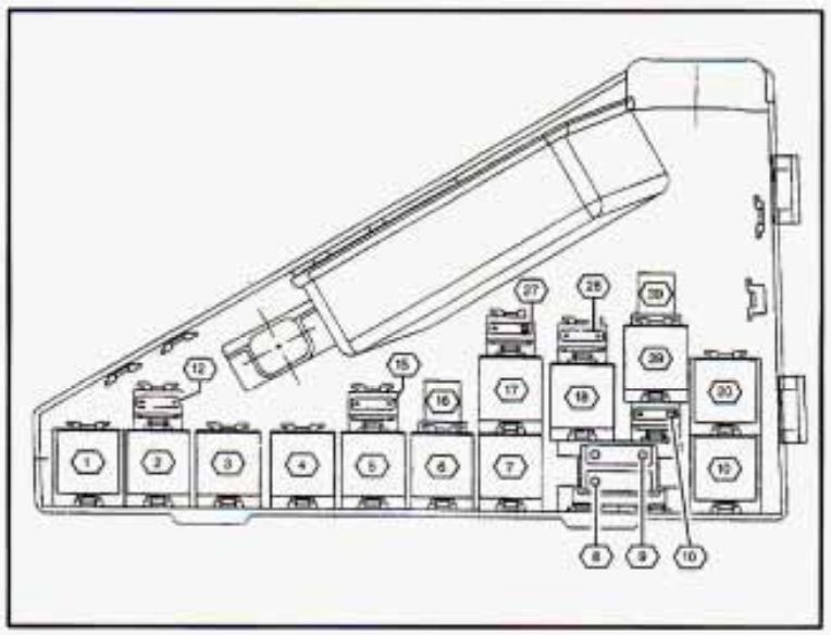
| № | Usage |
| 1 | Secondary Air Injection Pump (Relay K12) |
| 2 | Fan Control (Relay K67) |
| 3 | Auxiliary Water Pump (Relay K22) |
| 4 | Windshield Wiper Motor (Relay K8) |
| 5 | A/C Compressor Relay (K60) |
| 6 | Fan Control Relay (K87) |
| 7 | Fan Control Relay (K26) |
| 8 | Fan Control (Fuse 42) |
| 9 | Secondary Air Injection Pump (Fuse 49) |
| 10 | Engine Controls Power Relay (K43) |
| 12 |
Fan Control (Fuse 40) |
| 15 | Fan Control (Fuse 52) |
| 16 | Connector C110 |
| 17 | Fan Control (Relay K52) |
| 18 | Fan Control (Relay K28) |
| 19 | Fan Control Relay, Engine Control Module (ECM) Relay (Fuse 50) |
| 20 | Fuel Pump (Relay K44) |
| 27 | Heated Oxygen Sensors (Fuse 43) |
| 28 | Engine Control Module (ECM) (Fuse 60) |
| 29 | Engine Control Module (ECM) (Relay K48) |
| 39 | Coolant Fan Test Connect |
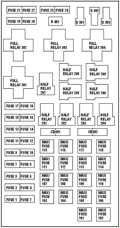
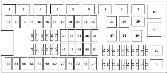
Version 2
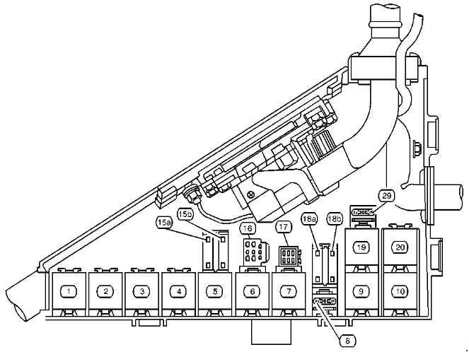
| № | Usage |
| 1 | Secondary Air Injection Pump (Relay K12) |
| 2 | Fan Control (Relay K67) |
| 3 | Auxiliary Water Pump (Relay K22) |
| 4 | Windshield Wiper Motor (Relay K8) |
| 5 | A/C Compressor Relay (K60) |
| 6 | Fan Control Relay (K87) |
| 7 | Fan Control Relay (K26) |
| 8 | Fuse 50 |
| 9 | Fan Control Relay (K28) |
| 10 | Engine Controls Power Relay (K43) |
| 15 | Fuse 40 (A) Fuse 52 (B) |
| 16 | Connector C110 |
| 17 | Coolant Fan Test Connector Fan Control |
| 18 | Fuse 42 (A), Fuse 49 (B) |
| 19 | Fan Control Relay (K52) |
| 20 | Fuel Pump Relay (K44) |
| 25 | Fuse 43 |
WARNING: Terminal and harness assignments for individual connectors will vary depending on vehicle equipment level, model, and market.