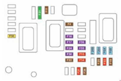
* The maxi fuses provide additional protection for the electrical systems.
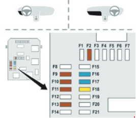
*According to modelWARNING: Terminal and harness assignments for individual connectors will vary depending on vehicle equipment level, model, and market.
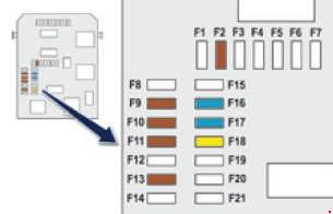
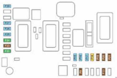
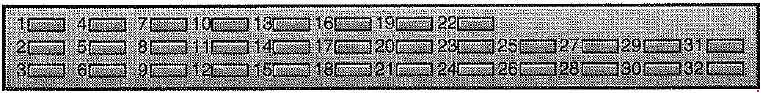
Engine control unit and fan assembly control relay supply, timing and canister electrovalves (1.6 l 16V THP), air fl ow sensor (Diesel), injection pump (Diesel), water in diesel sensor (Diesel), EGR electrovalves, air heating (Diesel)
Electric power steering, switching and protection unit (Diesel)
8
20(-09.07)
25(10.07-)
Starter motor control
9
10
ABS/ESP control unit, brake pedal switch
10
30
Engine control unit actuators (petrol: ignition coils, electrovalves, oxygen sensors, injectors, heaters, electronic thermostat) (Diesel: electrovalves, heaters)
11
40
Air conditioning blower
12
30
Windscreen wipers Low/High speed
13
40
Built-in systems interface supply (ignition positive)
14
30
Diesel heater (Diesel)
15
10
Left main beam headlamp
16
10
Right main beam headlamp
17
15
Left dipped beam headlamp
18
15
Right dipped beam headlamp
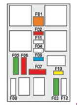
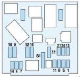
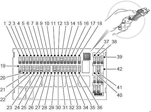
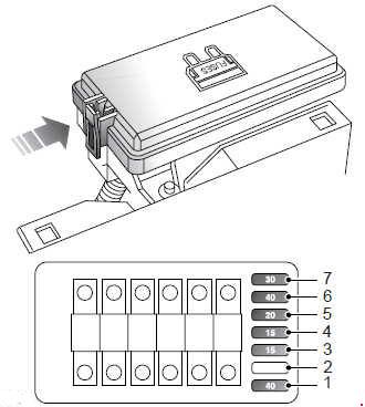
Maxi-fuse table
MF1
70
Fan assembly
MF2
20/30
ABS/ESP pump
MF3
20/30
ABS/ESP electrovalves
MF4
60
Built-in systems interface supply
MF5
60
Built-in systems interface supply
MF6
30
Additional fan assembly (1.6l 16V THP)
MF7
80
Passenger compartment fusebox
MF8
30
“2 Tronic” gearbox control unit
MF9
80
Heating unit (Diesel)
MF10
80
Electric power steering
MF11
40
Valvetronic electric motor (1.6l 16V THP)
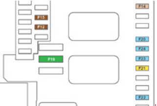
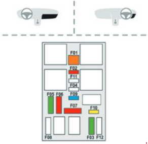
*According to modelWARNING: Terminal and harness assignments for individual connectors will vary depending on vehicle equipment level, model, and market.
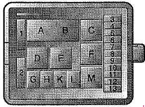
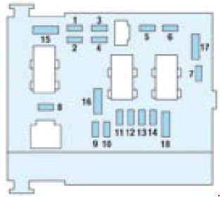
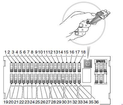
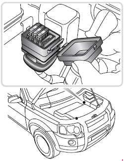
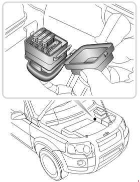
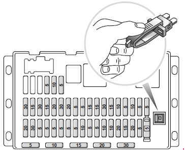
The fuse box is located under the fascia on the left-hand side of the vehicle.
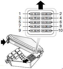
Peugeot 205 – fuse box diagram
№
A
Functions
1
10
Reverse lamp; tachometer*;
Dim lamps*;
Fuel gauge;
Water in fuel sensor (diesel);
Warning-lamps for: battery charge, water temperature, oil pressure, coolant level, brakes, choke; water in fuel (diesel)
2
25
Direction indicators;
Fuel gauge;
Seat heating*;
Additional heater/ventilation pump;
Gauges*;
Oil temperature;
Coolant temperature;
Oil pressure;
Heater/ventilation;
Air conditioning;
Warning lamps; battery charge, water in fuel, coolant temperature, oil pressure, coolant level, brakes, choke, ABS
3
25
Map reading lamp;
Brake lights;
Windscreen wipe/wash, front and rear;
Tachometer*;
Headlamp wash*;
Car radio (+ accessories);
Glovebox*;
Relay – window lift mechanism*;
Relay – rear screen demist;
Time-lag relay – interior lighting*
4
15
Spot lamps*
5
10
Hazard lamps
6
–
Not in use
7
25
Clock;
Interior lighting;
Boot lighting*;
Centralised lock* car radio (+ permanent);
Power supply to towbar;
Supply relay – window lift mechanism
8
30
Horn;
Rear screen demist; Cigar lighter
9
25
Front electric windows*
10
5
Rear fog lamp
11
5
Rear side lamps-left;
Licence plate lamp
12
5
Rear side lamp – right
13
5
Fascia panel lighting;
Front side lamps
14
15
Petrol feed pump*
* According to model or country
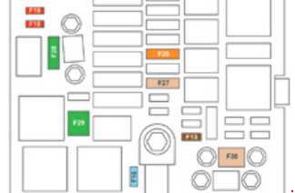
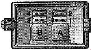
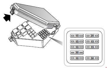
Peugeot 205 – fuse box diagram
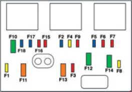
A set of fuses in the engine compartment serves protection of the following parts:
1 fuse, 30A – ABS* anti-lock system supply*
1 fuse, 30A – Engine fan
1 fuse, 10A – Lambda probe*
*According to modelWARNING: Terminal and harness assignments for individual connectors will vary depending on vehicle equipment level, model, and market.