AMC Gremlin (1970 – 1978) – fuse box diagram
Year of production: 1970, 1971, 1972, 1973, 1974, 1975, 1976, 1977, 1978
Type 1
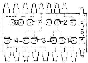
| No. |
A |
Protected Component |
| 1 | 9 | Dome light, cargo, courtesy, clock, glove box, and trunk light |
| 2 | 14 | Tail, park and instrument lights, light switch, windshield wiper, heater, cigar lighter, clock, license light, transmission, air conditioning thermostat, radio, tachometer, ash tray light, seat belt module and key buzzer |
| 3 | 20 | Stop light and hazard warning flasher |
| 4 | 20 | Turn signal, back-up lights and accessories |
| 5 | 2½ | Panel lights |
| 6 | 4 | Gauges |
| 7 | 20 | Fan |
|
Circuit Breaker:
|
||
Type 2
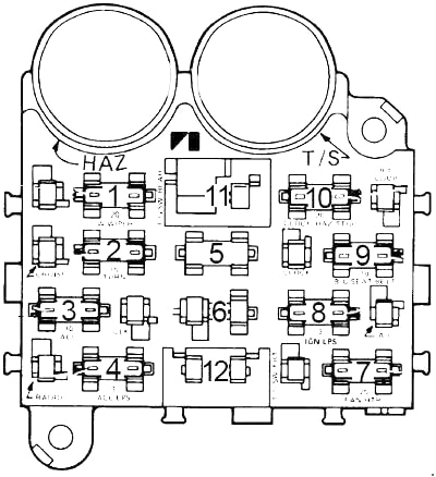
| No. |
A |
Protected Component |
| 1 | 10 | Parking lights, key/headlights warning buzzer |
| 2 | 15 | Stop light and hazard warning |
| 3 | – | – |
| 4 | 3 | Cluster illumination |
| 5 | – | – |
| 6 | – | – |
| 7 | 25 | Heater/blower motor, A/C clutch |
| 8 | 15 | Radio, cigar lighter |
| 9 | 15 | Turn signals, backup lights, windshield washers |
| 10 | 5 | Gauges, seat belt warning |
| 11 | 30 | Power door lock, power windows circuit breaker |
| 12 | 25 | Heated rear window |
Circuit Breaker:
|
||
WARNING: Terminal and harness assignments for individual connectors will vary depending on vehicle equipment level, model, and market.