Audi A1 (GB; 2019 – 2022) – fuse box diagram
Year of production: 2019, 2020, 2021, 2022
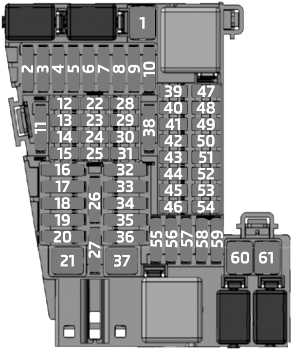
Instrument panel fuse box (-SC-)
The fuses are behind a cover on the driver’s side.
| № | Amps | Function / component |
|---|---|---|
| SC1 | – | – |
| SC2 | – | – |
| SC3 | 30A | Digital sound package control unit |
| SC4 | – | – |
| SC5 | – | – |
| SC6 | 40A | Onboard supply control unit |
| SC7 | – | – |
| SC8 | 30A | Fresh air blower control unit |
| SC9 | – | – |
| SC10 | – | – |
| SC11 | – | – |
| SC12 | 7.5A | Front left seat belt |
| SC13 | 7.5A | Light switch Rain and light sensor Anti-theft alarm sensor Control unit for cornering light and headlight range control Storage compartment illumination bulb Light 1 for dashboard ambient lighting Light 2 for dashboard ambient lighting Diagnostic connection Light for driver door ambient lighting Light for passenger door ambient lighting Light 2 for driver door ambient lighting Light 2 for front passenger door ambient lighting Front roof module |
| SC14 | – | – |
| SC15 | 7.5A | Control unit in dash panel insert Emergency call module control unit and communication unit |
| SC16 | 40A | Onboard supply control unit |
| SC17 | 30A | 2018: Front passenger door control unit Rear passenger door control unit 2019-2022: |
| SC18 | – | – |
| SC19 | 25A | Control unit 1 for information electronics |
| SC20 | 30A | Heated rear window relay |
| SC21 | – | – |
| SC22 | 7.5A | 2019-2022: Multimedia system operating unit |
| SC23 | 7.5A | Reversing camera system control unit |
| SC24 | 7.5A | Driver side volume regulator (2018-2019) Multimedia system operating unit (2018-2019) Charger 1 for mobile devices Aerial amplifier for mobile telephone USB hub |
| SC25 | 7.5A | 2019-2022: Driver side volume regulator |
| SC26 | 7.5A | Data bus diagnostic interface |
| SC27 | 7.5A | Electronically controlled damping control unit |
| SC28 | 7.5A | Ignition/starter switch Steering column electronics control unit |
| SC29 | 7.5A | Alarm horn |
| SC30 | 7.5A | Front right seat belt |
| SC31 | 15A | Heater and air conditioning controls |
| SC32 | 7.5A | Front left headlight |
| SC33 | 30A | 2018: Driver door control unit Control unit with rear driver side window regulator motor 2019-2022: |
| SC34 | 7.5A | Front right headlight |
| SC35 | 40A | Onboard supply control unit |
| SC36 | 20A | Dual tone horn relay |
| SC37 | 30A | Onboard supply control unit |
| SC38 | 30A | Onboard supply control unit |
| SC39 | 10A | Adaptive cruise control unit Parking aid control unit Blind Spot Monitor control unit Blind Spot Monitor control unit 2 Front camera for driver assist systems |
| SC40 | 7.5A | Interior mirror Centre switch module in dash panel Diagnostic connection |
| SC41 | 7.5A | Relay for power sockets |
| SC42 | 7.5A | Clutch position sender Pressure sender for refrigerant circuit Control unit for structure-borne sound Starter relay 1 Starter relay 2 |
| SC43 | 7.5A | Rear window wiper motor |
| SC44 | 7.5A | Airbag control unit Front roof module |
| SC45 | – | – |
| SC46 | 7.5A | Starter inhibitor and reversing lights switch |
| SC47 | 7.5A | Front roof module |
| SC48 | 7.5A | Entry and start authorisation control unit Control unit for electronic steering column lock |
| SC49 | – | – |
| SC50 | – | – |
| SC51 | – | – |
| SC52 | – | – |
| SC53 | 7.5A | Selector lever Ignition key withdrawal lock solenoid |
| SC54 | – | – |
| SC55 | – | – |
| SC56 | – | – |
| SC57 | – | – |
| SC58 | 20A | 12V socket |
| SC59 | – | – |
| SC60 | – | – |
| SC61 | – | – |
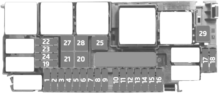
Engine Compartment Fuse Box (-SB-)
| № | Amps | Function / component |
|---|---|---|
| SB1 | 15A | Engine control unit |
| SB2 | 7.5A/10A | Charge air cooling pump (1.5L, 2.0L petrol) Continued coolant circulation pump (1.0L petrol) Vacuum pump relay (1.5L petrol) Exhaust flap control unit (1.5L petrol) Fuel metering valve (1.0L petrol) |
| SB3 | 15A | Lambda probe 1 before catalytic converter Lambda probe 1 after catalytic converter |
| SB4 | 15A | Fuel pump control unit Engine component current supply relay (2.0L petrol) |
| SB5 | 10A/15A | Oil level and oil temperature sender Activated charcoal filter solenoid valve 1 (1.0L, 1.5L petrol) Camshaft control valve 1 (1.0L, 1.5L petrol) Turbocharger air recirculation valve (2.0L petrol) Intake manifold flap valve (2.0L petrol) Exhaust camshaft control valve 1 (1.0L, 1.5L petrol) Valve for oil pressure control Piston cooling jet control valve Inlet cam actuator for cylinder 2 (1.5L petrol) Exhaust cam actuator for cylinder 2 (1.5L petrol) Inlet cam actuator for cylinder 3 (1.5L petrol) Exhaust cam actuator for cylinder 3 (1.5L petrol) Radiator fan |
| SB6 | 20A | Ignition coil 1~4 with output stage (1.0L, 1.5L petrol) |
| SB7 | 10A/15A | Vacuum pump for brakes (1.0L petrol) Vacuum pump relay (1.5L petrol) Coolant valve for gearbox (2.0L petrol) |
| SB8 | 10A | Actuator 1~8 for camshaft adjustment (2.0L petrol) Injector 2 for cylinder 1~4 (2.0L petrol) Engine component current supply relay (2.0L petrol) |
| SB9 | 7.5A | Brake light switch |
| SB10 | 7.5A | Battery monitor control unit |
| SB11 | – | – |
| SB12 | 10A | Ar conditioner compressor regulating valve |
| SB13 | 10A | Front drive battery module (with battery in luggage compartment) |
| SB14 | 7.5A | ABS control unit Main relay Engine control unit |
| SB15 | 30A | Mechatronic unit for dual clutch gearbox |
| SB16 | – | – |
| SB17 | 7.5A | Engine control unit |
| SB18 | 30A | Starter |
| SB19 | 30A | Wiper motor relay 1 Wiper motor relay 2 |
| SB20 | 60A | ABS control unit |
| SB21 | 25A | ABS control unit |
| SB22 | – | – |
| SB23 | – | – |
| SB24 | – | – |
| SB25 | – | |
| SB26 | 50A | Radiator fan (2.0L petrol) |
| F27 | – | – |
| F28 | – | – |
| F29 | – | – |
| F30 | – | – |
| F31 | – | – |
| F32 | – | – |
| F33 | – | – |
| F34 | – | – |
| F35 | 5A | Boost DC |
| F36 | – | – |
| F37 | – | – |
| F38 | 10A | FL_L (Front Lamp_Left) |
| F39 | 60A | IPB (Integrated Power Brake) |
| F40 | – | – |
| F41 | 20A | VTOV (Vehicle to Vehicle) |
| F42 | – | – |
| F43 | 25A | FR WIP (Front Wiper) |
| F44 | – | – |
| F45 | – | – |
| F46 | – | – |
| F47 | – | – |
| F48 | 200A | Battery |
| F49 | 60A | FAN |
| F50 | 100A | R-EPS (Rack-Electronic Power Steering) |
| F51 | 80A | IEC (Dashboard area fuse and relay box) |
| F52 | 80A | TEC (Trunk fuse and relay box) |
| K01 | – | |
| K02 | – | |
| K03 | IG4 relay | |
| K04 | – | |
| K05 | – | |
| K06 | – | |
| K07 | IG3 relay | |
| K08 | VTOV relay (Vehicle to Vehicle) | |
| K09 | – | |
| K10 | – | |
| K11 | – | |
| K12 | – |
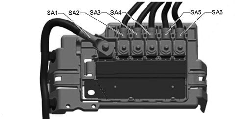
Main Fuses (-SA-)
| № | Amps | Function / component |
|---|---|---|
| SA1 | 350A | With front battery: Starter |
| SA1 | 200A | With rear battery: Alternator |
| SA2 | – | – |
| SA3 | 150A | Fuse holder B (-SB-) Fuses # 10, 16, 19, 24, 26 Main relay |
| 508 | – | Battery |
| SA4 | 80A | Fuse holder C (-SC-) Fuses # 12, 21 |
| SA5 | 125A | Fuse holder C (-SC-) Fuses # 28, 37 Relay for power sockets |
| SA6 | 80A | Power steering control unit |
WARNING: Terminal and harness assignments for individual connectors will vary depending on vehicle equipment level, model, and market.