Cadillac Seville (1979 – 1981) – fuse box diagram
Year of production: 1979, 1980, 1981
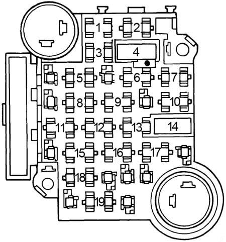
Fuse Box
| No. |
A |
Circuit Protected |
| 1 | 3 | Fuel injector |
| 2 | 3 | Fuel injector |
| 3 | 3 | Fuel pump cranking circuit |
| 4 | 20 | ECS battery |
| 5 | 10 | MDA ignition |
| 6 | 10 | Fuel pump |
| 7 | 15 | ECS ignition |
| 8 | – | – |
| No. |
A |
Circuit Protected |
| 1 | 10 | Cornering, side marker, opera, right door ash tray, instrument panel ash tray lights |
| 2 | 3 | Cruise control, DFI brake switch |
| 3 | 5 | Rheostat controlled instrument panel lig hts |
| 4 | – | – |
| 5 | 10 | Back-up lights, diesel fast idle, diesel controller |
| 6 | 20 | Air conditioning compressor feed, ECC programmer and power module, rear defogger relay coil, generator indicator |
| 7 | 10 | Antenna motor feed |
| 8 | 20 | Turn signal lights |
| 9 | 25 | Opera, license, tail and rear side marker lights |
| 10 | 20 | Stop light switch, hazard warning flasher, ECC control head |
| 11 | 20 | Fuel gauge, oil pressure and coolant temperature indicator, low brake fluid indicator, seat belt warning chime and indicator, electronic level control compressor, downshift switch |
| 12 | 20 | Key warning buzzer, coolant temperature indicator, instrument panel courtesy and compartment lights, cigar lighter, engine telltale light, glove box light |
| 13 | 25 | Automatic Temperature Control blower |
| 14 | – | – |
| 15 | 10 | Radio, antenna relay coil |
| 16 | 20 | Electronic fuel injection (’79) |
| 17 | 20 | Body courtesy lights, cigar lighters, level control height sensor, ash tray lights |
| 18 | 25 | Windshield wipers and low washer fluid indicator |
| 19 | 25 | Rear window defogger |
Circuit Breaker:
- Headlights (Twilight Sentinel) — Integral with headlight switch.
- Windshield Wiper — Integral with windshield wiper switch.
- Rear Defogger — Circuit breaker located on lower steering column cover reinforcement.
- Sunroof — 25 amp. On body bracket at upper right corner of fuse block
Fusible Link:
- Accessories & Body Feed — 16 gauge fusible link located in black/red stripe wire at starter
- Ignition — 16 gauge fusible link located in red wire at starter solenoid
- Headlights — 18 gauge fusible link located in yellow wire at starter
- Charging — 16 gauge fusible link located in red/white stripe wire at junction block
- Fuel Injection Electronic Control Unit – 18 gauge fusible link located in dark green wire on “BAT” terminal of alternator (’79).
In-Line Fuse:
- Vanity Mirror — 2 amp. fuse located behind mirror
- EFI Fuel Pump — 10 amp. fuse located left of fuel injection electronic control unit brown wire (’79)
- Theft Deterrent — One 20 amp. fuse for lights, and one 25 amp. fuse for horn is located above radio in instrument panel.
- Trunk Lid Pull Down — One 20 amp. fuse is located behind right hand fabric rear end panel inside trunk.
WARNING: Terminal and harness assignments for individual connectors will vary depending on vehicle equipment level, model, and market.