Mercedes-Benz CLS Class x218 (2010 – 2017) – fuse box diagram
Year of production: 2010, 2011, 2012, 2013, 2014, 2015, 2016, 2017
Fuse box in the engine compartment
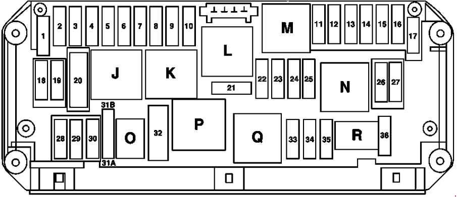
| Number | A | Description |
| 1 | 25 | Electronic Stability Program control unit Premium Electronic Stability Program control unit Blower motor Blower regulator |
| 2 | 30 | Left front door control unit |
| 3 | 30 | Right front door control unit |
| 4 | 20 | Valid with engine 157: Fuel system control unit |
| 5 | 7,5 | Instrument cluster Rear SAM control unit with fuse and relay module Exterior lights switch |
| 6 | 10 | Valid for diesel engine: CDI control unit |
| Valid for gasoline engine: ME-SFI control unit | ||
| 7 | 20 | Starter circuit 50 relay |
| 8 | 7,5 | Supplemental restraint system control unit |
| 9 | 15 | Center console socket |
| 10 | 30 | Wiper motor |
| 30 | Switched via wiper park position heater relay: Wiper park position heater | |
| 11 | 7,5 | Audio/COMAND display Audio/COMAND control panel |
| 12 | 7,5 | Automatic climate control control and operating unit Upper control panel control unit Automatic transmission transmission mode button Suspension button group |
| 13 | 7,5 | Steering column tube module control unit Multifunction camera Stereo multifunction camera |
| 14 | 7,5 | Electronic Stability Program control unit Premium Electronic Stability Program control unit |
| 15 | 7,5 | Supplemental restraint system control unit |
| 16 | 5 | Valid with engine 157: DIRECT SELECT INTERFACE |
| 17 | 30 | Electrical glass tilting/sliding roof: Overhead control panel control unit |
| 18 | 7,5 | Analog clock Backup relay |
| 19 | 20 | Electronic ignition lock control unit |
| 20 | 40 | Electronic Stability Program control unit Premium Electronic Stability Program control unit |
| 21 | 7,5 | Brake lights switch Glove compartment lamp switch Front passenger seat occupied recognition and ACSR Weight sensing system (WSS) control unit |
| 22 | 15 | Fan motor for internal combustion engine and air conditioning with integrated control Valid for diesel engine: CDI control unit Connector sleeve, circuit 87 Valid for gasoline engine: ME-SFI control unit Connector sleeve, circuit 87 M2e Valid with engine 276: Radiator shutters actuator |
| 23 | 20 | Valid for gasoline engine: Connector sleeve, circuit 87 M1i Valid for diesel engine: CDI control unit Connector sleeve, circuit 87 |
| 24 | 15 | Valid for diesel engine: Connector sleeve, circuit 87 Valid for engine 157, 276, 278: Connector sleeve, circuit 87 M1e |
| 25 | 15 | Valid for diesel engine: Oxygen sensor upstream of catalytic converter |
| Valid for gasoline engine: ME-SFI control unit | ||
| 26 | 20 | Radio Radio with auto pilot system COMAND controller unit |
| 27 | 7,5 | Valid for gasoline engine: ME-SFI control unit |
| 7,5 | Valid for diesel engine: CDI control unit Electronic ignition lock control unit |
|
| 28 | 7,5 | Instrument cluster |
| 29 | 10 | Right front lamp unit |
| 30 | 10 | Left front lamp unit |
| 31A | 15 | Switched through the horns relay: Left fanfare horn Right fanfare horn |
| 31B | 15 | Switched through the horns relay: Left fanfare horn Right fanfare horn |
| 32 | — | Secondary air injection relay |
| 33 | 10 | Fully integrated transmission control controller unit |
| 34 | 7,5 | Fuel system control unit |
| 35 | — | — |
| 36 | 7,5 | Night View Assist control unit DISTRONIC electric controller unit |
| Relay |
||
| J | Circuit 15 relay | |
| K | Terminal 15R relay | |
| L | Wiper park heater relay | |
| M | Starter circuit 50 relay | |
| N | Engine circuit 87 relay | |
| O | Horn relay | |
| P | — | |
| Q | Backup relay | |
| R | Chassis circuit 87 relay | |
Fuse box in the trunk
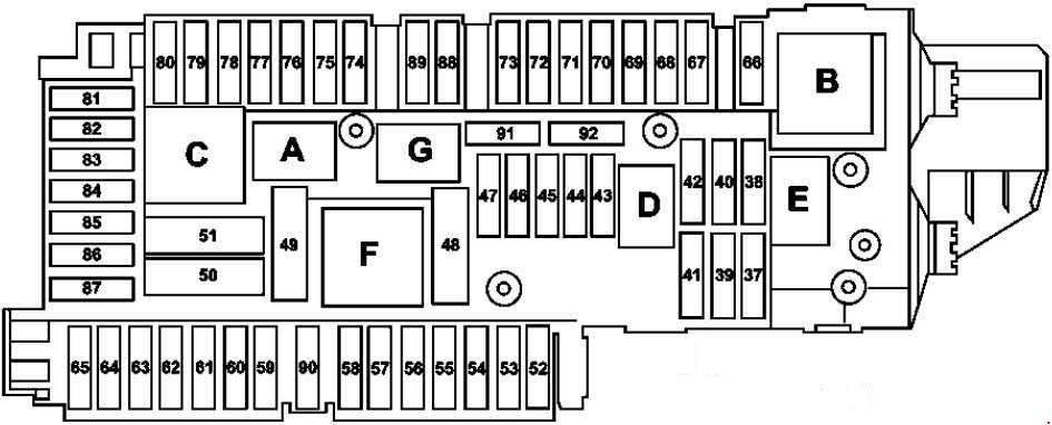
| Number | A | Description |
| 37 | 7,5 | Driver seat NECK-PRO head restraint solenoid Front passenger seat NECK-PRO head restraint solenoid |
| 38 | 15 | Shooting Brake: Connected through liftgate windshield wiper relay: Tailgate wiper motor |
| 39 | 30 | Valid for left-hand drive vehicles:Left rear door control unit Valid for right-hand drive vehicles: Left front door control unit |
| 40 | — | — |
| 41 | 30 | Valid for left-hand drive vehicles: Right front door control unit Valid for right-hand drive vehicles: Right rear door control unit |
| 42 | 25 | Fuel system control unit |
| 43 | 7,5 | Valid up to 31.08.2014: Telematics services communications module (Live Traffic Information) Valid as of 01.09.2014:Tire pressure monitor control unit |
| 44 | 30 | Front passenger seat adjustment switch |
| 45 | 30 | Driver seat adjustment switch |
| 46 | 7,5 | Alarm siren (Interior monitoring) Interior protection and tow-away protection control unit (Interior monitoring) Coupe: M 1, AM, CL [ZV] and KEYLESS-GO antenna amplifier Shooting Brake: Rear window antenna amplifier 1 Valid with engine 157, 276, 278 and USA version: Coolant circulation pump relay |
| 47 | — | — |
| 48 | — | — |
| 49 | 40 | Coupe: Switched through the rear window heater relay: Rear window heater Shooting Brake: Switched through the rear window heater relay: Rear window antenna amplifier 1 |
| 50 | 50 | Right front reversible emergency tensioning retractor |
| 51 | 50 | Left front reversible emergency tensioning retractor |
| 52 | — | — |
| 53 | 30 | Trailer recognition control unit |
| 54 | 15 | Trailer recognition control unit |
| 55 | — | — |
| 56 | 15 | Trailer socket |
| 57 | 25 | Trailer recognition control unit |
| 58 | 25 | Trailer recognition control unit |
| 59 | 7,5 | Left front bumper DISTRONIC (DTR) sensor Right front bumper DISTRONIC (DTR) sensor Left rear bumper radar sensor (Active Blind Spot Assist) Right rear bumper radar sensor (Active Blind Spot Assist) Left rear bumper intelligent radar sensor (Blind Spot Assist) Intelligent radar sensor for right rear bumper (Blind Spot Assist) |
| 60 | 7,5 | Multicontour seat pneumatic pump |
| 30 | Active multicontour seat pneumatic pump | |
| 61 | 40 | Coupe: Trunk lid control (KDS) control unit Shooting Brake: Liftgate control unit |
| 62 | 25 | Driver seat control unit |
| 63 | 25 | Rear seat heater control unit |
| 64 | 25 | Front passenger seat control unit |
| 65 | 7,5 | Up to 31.05.2012: Steering wheel heater control unit As of 01.06.2012: Steering column tube module control unit |
| 66 | 7,5 | Rear blower motor |
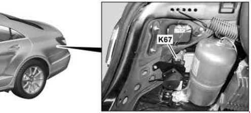
| 67 | 40 | Sound system amplifier control unit |
| 68 | 15 | AIRmatic control unit |
| 69 | 25 | Rear bass speaker amplifier |
| 70 | 5 | Tire pressure monitor control unit Valid as of 01.09.2014 with engine 157, 276, 278 without USA version:Coolant circulation pump relay |
| 71 | 15 | Vehicle interior socket, front |
| 72 | 15 | Cargo area socket |
| 73 | 5 | Valid with engine 157: Transmission mode control unit Stationary heater: Stationary heater radio remote control receiver |
| 74 | 15 | KEYLESS-GO control unit Valid as of 01.09.2014: Left front lamp unit Right front lamp unit |
| 75 | 20 | Stationary heater unit Valid as of 01.09.2014: Left front lamp unit Right front lamp unit |
| 76 | 15 | Rear center console socket |
| 77 | 7,5 | Weight sensing system (WSS) control unit Navigation processor |
| 78 | 7,5 | Media interface control unit |
| 79 | 5 | Video and radar sensor system control unit Valid as of 01.09.2014 with Driving assistance package Plus: Radar sensors control unit Chassis gateway control unit |
| 80 | 5 | Parking system control unit |
| 81 | 5 | Cellular telephone system antenna amplifier / compensator Mobile phone electrical connector |
| 82 | 7,5 | Left front seat ventilation blower regulator Right front seat ventilation blower regulator |
| 83 | 7,5 | Reversing camera Navigation processor Emergency call system control unit |
| 84 | 5 | Reversing camera control unit Reversing camera power supply module Reversing camera SDAR/high definition tuner control unit Digital Audio Broadcasting control unit |
| 85 | 7,5 | TV tuner (analog/digital) Digital TV tuner |
| 86 | — | — |
| 87 | 7,5 | Emergency call system control unit Valid up to 31.08.2014 with engine 157, 276, 278 without USA version:Coolant circulation pump relay Valid to 31.05.2016 with Live Traffic Information or eCall Europe emergency call system: Telematics services communications module Valid as of 01.06.2016: HERMES control unit Valid as from 01.06.2016 with Comfort telephony and Remote control for stationary heater: Antenna changeover switch for telephone and stationary heater |
| 88 | 15 | Intelligent servo module for DIRECT SELECT |
| 89 | 30 | Trailer recognition control unit Valid with engine 157: Fuel system control unit |
| 90 | — | — |
| 91 | — | — |
| 92 | 15 | KEYLESS-GO control unit |
| Relay | ||
| A | Circuit 15 relay | |
| B | Circuit 15R relay (1) | |
| C | Heated rear window relay | |
| D | Valid for diesel engine: Fuel pump relay | |
| E | Shooting Brake: Liftgate windshield wiper relay Electrically adjustable front seats memory package: Seat adjustment relay |
|
| G | Circuit 15R relay (2) | |
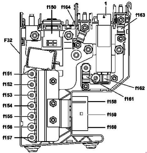
Front prefuse box
Without ECO start/stop
ECO start/stop
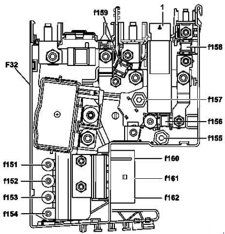
| Number | A | Description |
| 150 | — | ECO start/stop function: Pyrofuse 150 |
| 151 | 60 | Electrical power steering control unit |
| 152 | 60 | Front SAM control unit with fuse and relay module |
| 153 | 100 | — |
| 154 | 100 | Fan motor for internal combustion engine and air conditioning with integrated control (M4/7) |
| 155 | 150 | Valid for diesel engine: PTC heater booster |
| 156 | — | — |
| 157 | 150 | Front SAM control unit with fuse and relay module |
| 158 | 50 | Valid for left-hand drive vehicles: Blower regulator Valid for right-hand drive vehicles without DISTRONIC PLUS or without engine 157: Electronic Stability Program control unit Valid with right-hand drive vehicles with DISTRONIC PLUS or with engine 157: Premium Electronic Stability Program control unit |
| 159 | 50 | Valid for right-hand drive vehicles without DISTRONIC PLUS or without engine 157: Electronic Stability Program control unit Valid with right-hand drive vehicles with DISTRONIC PLUS or with engine 157: Premium Electronic Stability Program control unit |
| 160 | 60 | AlRmatic relay |
| 161 | — | — |
| 162 | 100 | Front SAM control unit with fuse and relay module |
| 163 | 150 | Without ECO start/stop function: Rear SAM control unit with fuse and relay module |
| 164 | 100 | Without ECO start/stop: Rear SAM control unit with fuse and relay module |
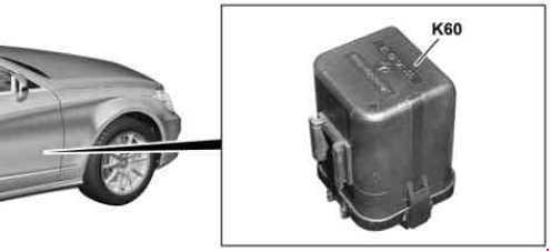
Coolant circulation pump relay
AIRMATIC relay
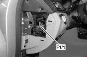
The Instrument Panel Fuse Panel
| Fused function | A |
| Protects the connection between the additional battery and the electronic ignition lock control unit and the front SAM control unit (for engine 276 as of 01.09.2014 or with engine 274) | 5 |
Additional battery relay and fuse
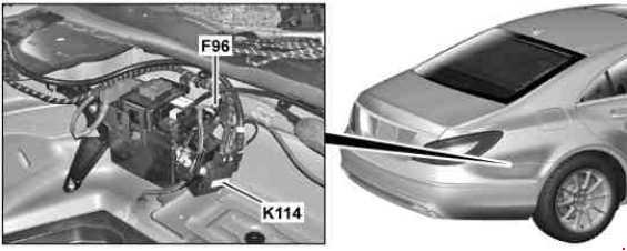
| Number | Description |
| F96 | Additional battery circuit 30 fuse |
| K114 | ECO start/stop function additional battery relay |
WARNING: Terminal and harness assignments for individual connectors will vary depending on vehicle equipment level, model, and market.