Mercedes-Benz E-Class w212 (2009 – 2016) – fuse box diagram
Year of production: 2009, 2010, 2011, 2012, 2013, 2014, 2015, 2016
Fuse Panel
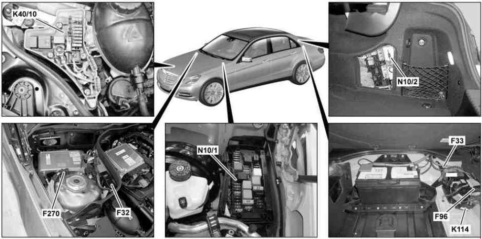
F32 – Front electrical prefuse box
F33 – Rear prefuse box (engine 273.9)
F96 – Additional battery circuit 30 fuse (7,5 A)(with ECO start/stop )
F270 – Additional battery protection (Hybrid)
K40/10 – HYBRID fuse and relay module (Hybrid)
K114 – ECO start/stop function additional battery relay
N10/1 – Front SAM control unit with fuse and relay module
N10/2 – Rear SAM control unit with fuse and relay module
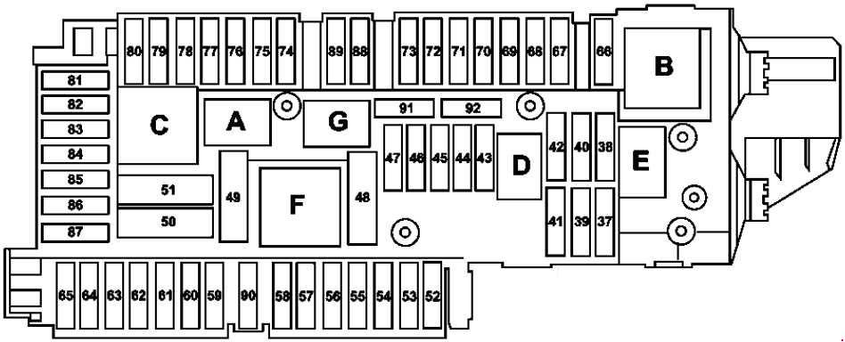
Fuse box in the engine compartment

| Fuse | A | Circuit protected |
| 1 | 25 | Valid for left-hand drive vehicle: Electronic Stability Program control unit Premium Electronic Stability Program control unit Hybrid: Regenerative braking system control unit Valid for right-hand drive vehicles: Blower regulator |
| 2 | 30 | up to 31.05.2010: Left front door control unit Valid for right-hand drive vehicles as of 01.06.2010: Left rear door control unit |
| 3 | 30 | up to 31.05.2010: Right front door control unit Valid for left-hand drive vehicles as of 01.06.2010: Right rear door control unit |
| 4 | 20 | Valid with engine 157: Fuel system control unit Valid for engine 642, 651 up to 31.05.2010: Fuel filter condensation sensor with heating element |
| 7,5 | Valid for engine 651 (with retrofitted heated fuel filter) up to 31.05.2010:Control unit for fuel filter condensation sensor with heating element | |
| 5 | 7,5 | Instrument cluster Exterior lights switch Rear SAM control unit with fuse and relay module Valid as of 01.03.2013: Electronic Stability Program control unit Valid as of 01.03.2013: Premium Electronic Stability Program control unit |
| 6 | 10 | Valid for diesel engine: CDI control unit Valid for gasoline engine: ME-SFI control unit Valid for engine 271.958, 274.920: CNG control unit |
| 7 | 20 | Starter |
| 8 | 7,5 | Supplemental restraint system control unit |
| 9 | 15 | Glove compartment socket |
| 10 | 30 | Wiper motor Wiper park position heater |
| 11 | 7,5 | Audio/COMAND display Audio/COMAND control panel Navigation module Cradle for navigation module COMAND fan motor |
| 12 | 7,5 | ACC control and operating unit Upper control panel control unit Valid for transmission 722, 724, 725: Automatic transmission transmission mode button AIRMATIC: Suspension button group |
| 13 | 7,5 | Steering column tube module control unit Multifunction camera Stereo multifunction camera |
| 14 | 7,5 | Electronic Stability Program control unit Premium Electronic Stability Program control unit |
| 15 | 7,5 | Supplemental restraint system control unit |
| 16 | 5 | Hybrid: Electrical refrigerant compressor Valid with transmission 722.930/931: DIRECT SELECT INTERFACE Valid for transmission 722 (except 722.930/931): Electronic selector lever module control unit |
| 17 | 30 | Overhead control panel control unit Panoramic sliding roof control module |
| 18 | 7,5 | Exterior lights switch Hybrid: Power electronics control unit Valid up to 28.02.2013: Instrument panel switch group Upper control panel control unit Valid for transmission 722 with ECO start/stop: Transmission oil auxiliary pump relay |
| 19 | 20 | Valid except transmission 722.9: Electronic ignition lock control unit Electric steering lock control unit |
| 20 | 40 | Valid for left-hand drive vehicle: Electronic Stability Program control unit Premium Electronic Stability Program control unit Valid for left-hand drive vehicle, Hybrid: Regenerative braking system control unit |
| 21 | 7,5 | Front passenger seat occupied recognition and ACSR Weight sensing system (WSS) control unit except Hybrid up to 28.02.2013:Brake lights switch Hybrid up to 28.02.2013: Hybrid brake light switch Switched through glove compartment lamp switch Glove compartment lamp |
| 22 | 15 | Valid for fan motor with 650, 800 W: Fan motor for internal combustion engine and air conditioning with integrated control Valid for engine 156: Electrical connector for interior harness and engine wiring harness Circuit 87 M2e connector sleeve Valid for engine 157, 271, 272, 273, 274, 276, 278: Electrical connector for interior harness and engine wiring harness Valid for engine 271, 272.98, 274.9, 276 and engine 651 (except with 4MATIC): Radiator shutters actuator Valid for engine 642, 651: CDI control unit Electrical connector for interior harness and engine wiring harness |
| 23 | 20 | Valid for diesel engine: Rear SAM control unit with fuse and relay module Valid for engine 271, 642, 651: Circuit 87 M1e connector sleeve Valid for engine 156, 157, 271, 272, 273, 274, 276, 278, 642, 651:Electrical connector for interior harness and engine wiring harness Valid for engine 271: ME-SFI control unit |
| 24 | 15 | Valid for engine 156, 157, 271, 272, 273, 274, 276, 278, 642, 651:Electrical connector for interior harness and engine wiring harness Valid for diesel engine: CDI control unit Valid for gasoline engine: ME-SFI control unit Valid for engine 271.958, 274.920: CNG control unit |
| 25 | 15 | Valid for engine 642, 651 with BlueTEC: Nitrogen oxides control unit downstream of diesel particulate filter Nitrogen oxides control unit downstream of the SCR catalytic converter Soot particulate sensor control unit Valid for gasoline engine: ME-SFI control unit Hybrid: Transmission cooling coolant circulation pump relay HYBRID power electronics coolant circulation pump relay Valid for engine 156: Connector sleeve, circuit 87 M3e |
| 26 | 20 | Radio Radio with auto pilot system COMAND controller unit |
| 27 | 7,5 | Valid for gasoline engine: ME-SFI control unit Valid for diesel engine: CDI control unit Electronic ignition lock control unit Valid for engine 271.958, 274.920: CNG control unit |
| 28 | 7,5 | Instrument cluster |
| 29 | 10 | Valid up to 28.02.2013: Right front lamp unit |
| 30 | 10 | Valid up to 28.02.2013: Left front lamp unit |
| 31A | 15 | Left fanfare horn Right fanfare horn |
| 31B | 15 | Left fanfare horn Right fanfare horn |
| 32 | 40 | Valid for engine 272: Electric air pump |
| 33 | 10 | Valid for transmission 722.6: Electronic transmission control control unit Valid for transmission 722.9, 724, 725: Fully integrated transmission control controller unit |
| 34 | 7,5 | Valid for engine 156, 271, 272, 273, 642, 651: Fuel system control unit |
| 35 | 7,5 | Hybrid: HYBRID control unit power supply relay |
| 36 | 7,5 | Night View Assist control unit Valid up to 28.02.2013: DISTRONIC electric controller unit Valid as of 01.03.2013: Front long-range radar sensor Valid as of 01.03.2013: COLLISION PREVENTION ASSIST controller unit |
| Relay | ||
| J | Circuit 15 relay | |
| K | Circuit 15R relay | |
| L | Wiper park position heater relay | |
| M | Starter circuit 50 relay | |
| N | Engine circuit 87 relay | |
| O | Horn relay | |
| P | Valid for engine 272: Secondary air injection relay | |
| Q | Transmission oil auxiliary pump relay | |
| R | Chassis circuit 87 relay | |
Fuse box in the trunk
| No. | Circuit protected | A |
| 37 | Driver seat NECK-PRO head restraint solenoid Front passenger seat NECK-PRO head restraint solenoid |
7,5 |
| 38 | Valid for model 212.2: Tailgate wiper motor | 15 |
| 39 | up to 31.05.2010: Left rear door control unit Valid for right-hand drive vehicles as of 01.06.2010: Left front door control unit |
30 |
| 40 | Spare | — |
| 41 | up to 31.05.2010: Right rear door control unit Valid for left-hand drive vehicles as of 01.06.2010: Right front door control unit |
30 |
| 42 | Fuel pump relay Valid for engine 156, 271, 272, 273, 274, 276, 278, 642, 651: Fuel system control unit |
25 |
| 43 | Telematics services communications module | 7,5 |
| 44 | Front passenger seat partially electric seat adjustment switch | 30 |
| 45 | Driver seat partially electric seat adjustment switch | 30 |
| 46 | FM 1, AM, CL [ZV] and KEYLESS-GO antenna amplifier Rear window antenna amplifier 1 DAB band III antenna Alarm siren Interior protection and tow-away protection control unit Valid as of 01.06.2011 on engine 157, 276, 278: Coolant circulation pump relay |
7,5 |
| 47 | Spare | — |
| 48 | Spare | — |
| 49 | Rear window heater | 40 |
| 50 | Right front reversible emergency tensioning retractor | 50 |
| 51 | Left front reversible emergency tensioning retractor | 50 |
| 52 | Spare | — |
| 53 | Trailer recognition control unit | 30 |
| 54 | Trailer recognition control unit | 15 |
| 55 | Spare | — |
| 56 | Trailer socket | 15 |
| 57 | Trailer recognition control unit | 20 |
| Left front illuminated door sill molding voltage converter Right front illuminated door sill molding voltage converter |
7,5 | |
| 58 | Trailer recognition control unit | 25 |
| 59 | Left front bumper DISTRONIC (DTR) sensor Right front bumper DISTRONIC (DTR) sensor |
7,5 |
| 60 | Multicontour seat pneumatic pump | 7,5 |
| Dynamic multicontour seat pneumatic pump | 30 | |
| 61 | Trunk lid control control unit Tailgate control control unit |
40 |
| 62 | Driver seat control unit | 25 |
| 63 | Rear seat heater control unit | 25 |
| 64 | Front passenger seat control unit | 25 |
| 65 | up to 28.02.2013: Steering wheel heater control unit | 7,5 |
| as of 01.03.2013: Steering column tube module control unit | 10 | |
| 66 | Rear blower motor | 7,5 |
| 67 | Sound system amplifier control unit | 40 |
| 68 | AIRmatic control unit Rear axle electronic level control control unit |
15 |
| 69 | Rear bass speaker amplifier | 25 |
| 70 | Tire pressure monitor control unit | 5 |
| 71 | Vehicle interior socket, front Front cigarette lighter with ashtray illumination |
15 |
| 72 | Cargo area socket | 15 |
| 73 | Diagnostic connector Stationary heater radio remote control receiver Valid with transmission 722.930/931: Transmission mode control unit |
5 |
| 74 | KEYLESS-GO control unit Valid as of 01.03.2013: Right front lamp unit Valid as of 01.03.2013: Left front lamp unit Valid as of 01.12.2011: DC/AC converter control unit |
15 |
| 75 | Stationary heater unit Valid as of 01.03.2013 (with Dynamic LED headlamps: Left front lamp unit Right front lamp unit |
20 |
| Valid for engine 156: Oil cooler fan motor relay | 25 | |
| 76 | Rear cup holder Rear center console socket Rear USB electrical connection |
15 |
| 77 | Rear cup holder Valid until 28.02.2013: Weight sensing system (WSS) control unit Valid for China, South Korea vehicles: Navigation processor |
7,5 |
| 78 | Media interface control unit Multimedia connection unit |
7,5 |
| 79 | Valid up to 31.05.2010: Radar sensors control unit Valid as of 01.06.2010: Video and radar sensor system control unit Valid as of 01.03.2013: Chassis gateway control unit |
5 |
| 80 | Parking system control unit | 5 |
| 81 | Cellular telephone system antenna amplifier / compensator Mobile phone electrical connector Navigation processor |
5 |
| 82 | Left front seat ventilation blower regulator Right front seat ventilation blower regulator |
10 |
| 83 | Circuit 15R connector sleeve Emergency call system control unit Valid until 31.05.2010: Navigation processor Japan version: Electronic Toll Collection control unit |
7,5 |
| 84 | Reversing camera power supply module Digital Audio Broadcasting control unit Valid up to 28.02.2013: Reversing camera control unit Valid as of 01.03.2013: Reversing camera Valid up to 31.05.2010: SDAR/high definition tuner control unit Valid as of 01.06.2010: Satellite digital audio radio (SDAR) control unit Valid as of 01.03.2013: 360° camera control unit |
5 |
| 85 | Valid until 28.02.2015: TV tuner (analog/digital) Valid until 28.02.2015 : Digital TV tuner Valid as of 01.03.2015: Tuner unit |
7,5 |
| 86 | DVD player Left rear display Right rear display |
7,5 |
| 87 | Emergency call system control unit Special vehicle multifunction control unit (SVMCU) Valid as of 01.06.2011 with engine 157, 274, 276, 278: Coolant circulation pump relay Valid as of 01.03.2015: Telematics services communications module |
7,5 |
| 88 | Valid with transmission 722.9: Intelligent servo module for DIRECT SELECT | 15 |
| 89 | Trailer recognition control unit Special vehicle multifunction control unit (SVMCU) Valid up to 28.02.2013 with engine 157: Fuel system control unit Valid as of 01.03.2013 (with Static LED headlamps): Right front lamp unit Left front lamp unit |
30 |
| 90 | Coolant circulation pump relay Valid for engine 642.8 with BlueTEC: AdBlue® fuse block |
40 |
| 91 | Valid for transmission 722 with ECO start/stop function: Front SAM control unit with fuse and relay module | 10 |
| 92 | Valid as of 01.03.2013: KEYLESS-GO control unit Valid as of 01.03.2013: Rear switching module Valid until 30.11.2011: DC/AC converter control unit |
15 |
| Relay |
||
| A | Circuit 15 relay | |
| B | Circuit 15R relay (1) | |
| C | Rear window heater relay | |
| D | Valid for diesel engine: Fuel pump relay | |
| E | Liftgate windshield wiper relay | |
| F | Seat adjustment relay | |
| G | Circuit 15R relay (2) | |
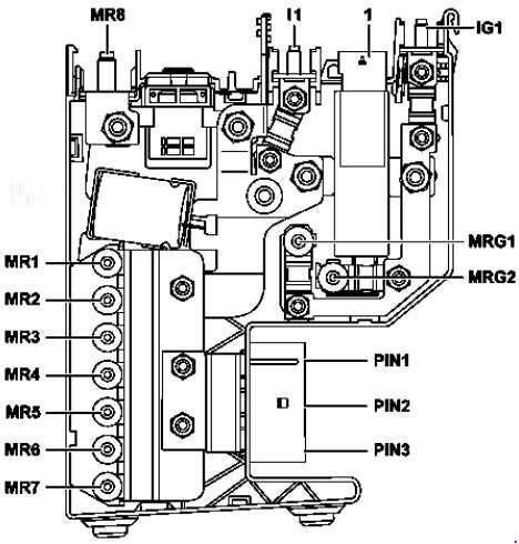
Front electrical prefuse box
| No. | Fused component | A |
| MR8 | Pyrofuse, triggered by Supplemental Restraint System control unit | — |
| MR1 | Electrical power steering control unit | 50 |
| MR2 | Spare | — |
| MR3 | Spare | — |
| MR4 | Fan motor for internal combustion engine and air conditioning with integrated control | 100 |
| MR5 | Valid for diesel engine: PTC heater booster | 150 |
| MR6 | Valid for front on-board electrical system battery: Front SAM control unit with fuse and relay module | 60 |
| MR7 | Front SAM control unit with fuse and relay module | 150 |
| PIN1 | Valid for left-hand drive vehicles: Blower regulator Valid for right-hand drive vehicles: Electronic Stability Program control unit Premium Electronic Stability Program control unit |
50 |
| PIN2 | Valid for right-hand drive vehicles: Electronic Stability Program control unit Premium Electronic Stability Program control unit |
50 |
| PIN3 | AIRmatic relay Valid with transmission 725: Fully integrated transmission control unit |
60 |
| MRG1 | Spare | — |
| MRG2 | Front SAM control unit with fuse and relay module | 100 |
| IG1 | Rear SAM control unit with fuse and relay module | 150 |
| I1 | Valid for front on-board electrical system battery: Rear SAM control unit with fuse and relay module | 100 |
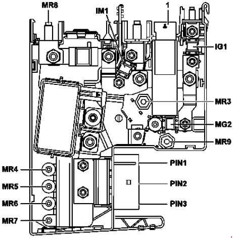
Front electrical prefuse box (with ECO start/stop)
| No. | Fused component | A |
| MR8 | Alternator Stationary heater control unit |
350 |
| MR4 | Fan motor for internal combustion engine and air conditioning with integrated control | 100 |
| MR5 | Valid for diesel engine: PTC heater booster | 150 |
| MR6 | Valid for front on-board electrical system battery: Front SAM control unit with fuse and relay module | 60 |
| MR7 | Front SAM control unit with fuse and relay module | 150 |
| MR9 | Spare | — |
| MG2 | Front SAM control unit with fuse and relay module | 100 |
| MR3 | Electrical power steering control unit | 80 |
| IG1 | Rear SAM control unit with fuse and relay module | 150 |
| IM1 | Valid for front on-board electrical system battery: Rear SAM control unit with fuse and relay module | 100 |
| PIN1 | Valid for left-hand drive vehicles: Blower regulator Valid for right-hand drive vehicles: Electronic Stability Program control unit Premium Electronic Stability Program control unit |
50 |
| PIN2 | Valid for right-hand drive vehicles: Electronic Stability Program control unit Premium Electronic Stability Program control unit |
50 |
| PIN3 | AIRmatic relay Valid with transmission 725: Fully integrated transmission control unit |
60 |
Front electrical prefuse box (Hybrid)
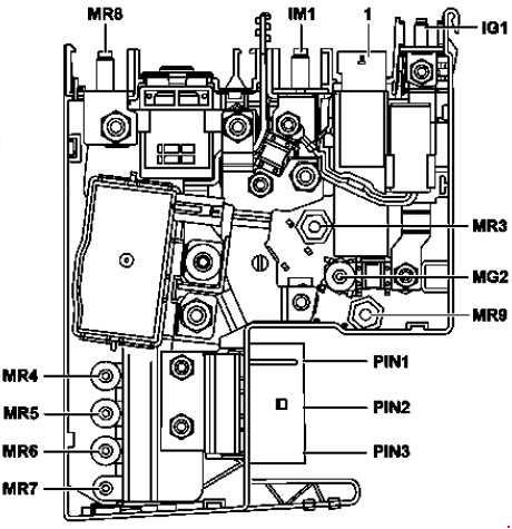
| No. | Fused component | A |
| MR8 | Pyrofuse, triggered by Supplemental Restraint System control unit | — |
| MR4 | Fan motor for internal combustion engine and air conditioning with integrated control | 100 |
| MR5 | Valid for diesel engine: PTC heater booster | 150 |
| MR6 | Valid for front on-board electrical system battery: Front SAM control unit with fuse and relay module | 60 |
| MR7 | Front SAM control unit with fuse and relay module | 150 |
| MR9 | HYBRID fuse and relay module | 150 |
| MG2 | Front SAM control unit with fuse and relay module | 100 |
| MR3 | Electrical power steering control unit | 80 |
| IG1 | Rear SAM control unit with fuse and relay module | 150 |
| IM1 | Valid for front on-board electrical system battery: Rear SAM control unit with fuse and relay module | 100 |
| PIN1 | Valid for left-hand drive vehicles: Blower regulator Valid for right-hand drive vehicles: Regenerative braking system control unit |
50 |
| PIN2 | Valid for right-hand drive vehicles: Regenerative braking system control unit | 50 |
| PIN3 | AIRmatic rela | 60 |
Rear prefuse box
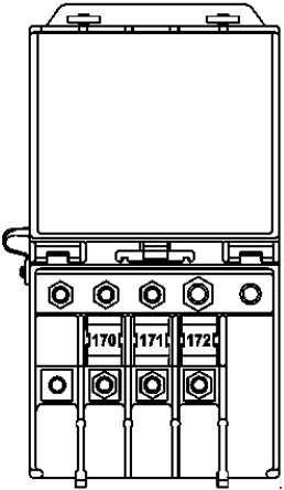
| No. | Fused component | A |
| 170 | Reserve | — |
| 171 | Front SAM control module with fuse and relay module | 60 |
| 172 | Rear SAM control unit with fuse and relay module | 100 |
AdBlue fuse block
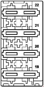
| No. | Fused component | A |
| 19 | AdBlue® control unit | 15 |
| 20 | AdBlue® control unit | 20 |
| 21 | AdBlue® control unit | 7,5 |
| 22 | AdBlue® control unit | 5 |
HYBRID fuse and relay module
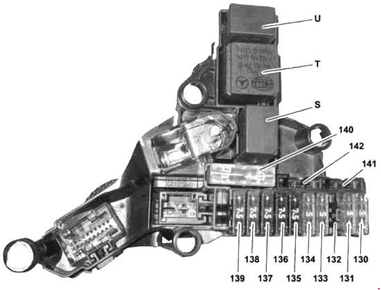
| No. | Fused component | A |
| 130 | Regenerative braking system control unit | 5 |
| 131 | Regenerative braking system control unit | 5 |
| 132 | Spare | — |
| 133 | Power electronics control unit | 5 |
| 134 | Vacuum pump relay (-) | 5 |
| 135 | Battery management system control unit | 7,5 |
| 136 | Pyrotechnical separator | 7,5 |
| 137 | Power electronics circulation pump 1 | 7,5 |
| 138 | Power electronics circulation pump 2 | 7,5 |
| 139 | Valid for engine 651: Transmission cooling coolant circulation pump | 7,5 |
| 140 | Vacuum pump relay (+) | 40 |
| 141 | Spare | — |
| 142 | Spare | — |
| Relay |
||
| S | Transmission cooling coolant circulation pump relay |
|
| T | HYBRID control unit power supply relay | |
| U | HYBRID power electronics coolant circulation pump relay | |
Oil cooler fan motor relay (engine 157)
Relay
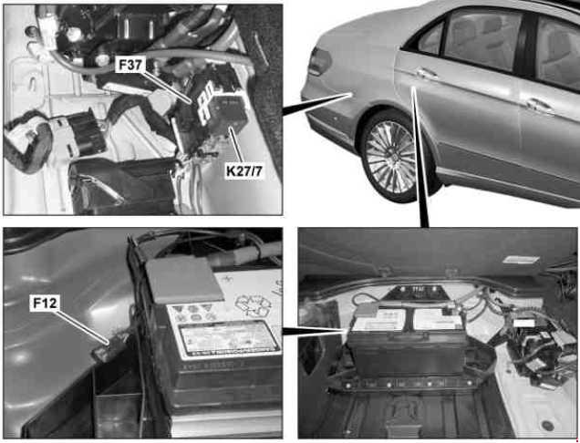
F12 – Stationary heater fuse (Hybrid)
F37 – AdBlue® fuse block (with engine 642.8 with BlueTEC)
K27/7 – AdBlue® supply relay (with engine 642.8 with BlueTEC)
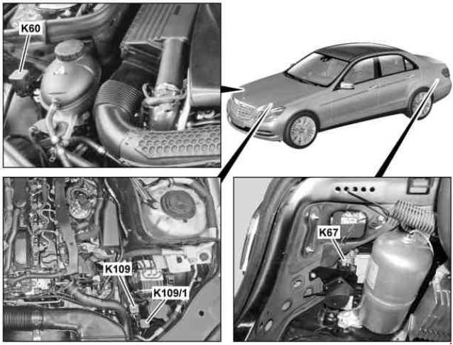
K60 – Coolant circulation pump relay (as of 01.06.2011 with engine 157, 274, 276, 278)
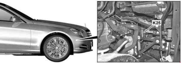
K67 – AIRMATIC relay
K109 – Vacuum pump relay (+) (Hybrid)
K109/1 – Vacuum pump relay (-) (Hybrid)
WARNING: Terminal and harness assignments for individual connectors will vary depending on vehicle equipment level, model, and market.

