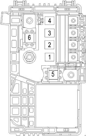
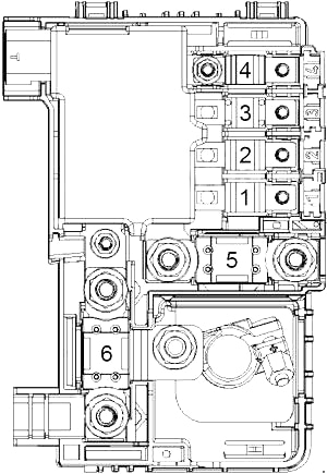
| No. |
A |
Protected Component |
| 1 |
15 |
Transmission Control Module (TCM) |
| 2 |
10 |
2.5L LKW: Air Conditioning Compressor Clutch Relay |
| 5 |
2.4L LUK, 2.0L LTG: Engine Control Module (ECM) |
| 3 |
10 |
2.4L LUK, 2.0L LTG: Air Conditioning Compressor Clutch Relay |
| 4 |
5 |
2.5L LKW: Engine Control Module (ECM) |
| 5 |
5 |
2.4L LUK, 2.0L LTG: Engine Control Module (ECM) |
| 6 |
25 |
Windshield Wiper Relay, Windshield Wiper Speed Control Relay |
| 7 |
5 |
2.5L LKW: Engine Control Module (ECM) |
| 8 |
15 |
– |
| 9 |
15 |
Ignition Coils |
| 10 |
20 |
Engine Control Module (ECM) |
| 11 |
10 |
2.5L LKW, 2.0L LTG: Multifunction Intake Air Sensor, Heated Oxygen Sensor |
| 12 |
40 |
2.5L LKW: Starter Relay No.2 |
| 30 |
2.4L LUK, 2.0L LTG: Starter Relay |
| 13 |
7.5 |
2.5L LKW, 2.0L LTG: Chassis Control Module, Control Solenoid Valve Assembly, Fuel Pump Driver Control Module |
| 7.5 |
2.4L LUK: Control Solenoid Valve Assembly |
| 14 |
10 |
2.4L LUK: Auxiliary Heater Coolant Pump |
| 15 |
10 |
2.4L LUK: Starter/Generator Coolant Pump Relay |
| 16 |
7.5 |
2.5L LKW, 2.0L LTG: Active Grille Air Shutter Actuator |
| 7.5 |
2.4L LUK: Starter/Generator Control Module, Active Grille Air Shutter Actuator |
| 17 |
5 |
Inflatable Restraint Sensing and Diagnostic Module |
| 18 |
5 |
2.5L LKW: Battery Isolator Control Module |
| 19 |
– |
– |
| 20 |
25 |
2.5L LKW: Transmission Fluid Pump Relay (Auxiliary) |
| 21 |
30 |
Rear Power Window |
| 22 |
30 |
Sunroof Motor |
| 23 |
7.5 |
2.4L LUK: Starter/Generator Control Module |
| 24 |
30 |
Front Power Window |
| 25 |
30 |
Keyless Entry Control Module |
| 26 |
60 |
Electronic Brake Control Module (ABS – Pump) |
| 27 |
30 |
– |
| 28 |
40 |
Rear Window Defogger |
| 29 |
15 |
Seat Lumbar Support Switch (Driver) |
| 30 |
15 |
Seat Lumbar Support Switch (Passenger) |
| 31 |
15 |
2.5L LKW, 2.0L LTG: Chassis Control Module |
| 15 |
2.4L LUK: Hybrid/EV Battery Pack Cooling Fan |
| 32 |
15 |
Body Control Module (Back-Up Lamps, Interior Lamp) |
| 33 |
25 |
Seat Heating Control Module, Seat Memory Control Module |
| 34 |
25 |
Electronic Brake Control Module (ABS – Valve) |
| 35 |
30 |
Audio Amplifier |
| 36 |
– |
– |
| 37 |
10 |
Right Headlamp (High Beam), High Beam Solenoid Actuator (Right) |
| 38 |
10 |
Left Headlamp (High Beam), High Beam Solenoid Actuator (Left) |
| 39 |
– |
– |
| 40 |
– |
– |
| 41 |
– |
– |
| 42 |
30 |
Cooling Fan High Speed Relay |
| 43 |
– |
– |
| 44 |
20 |
2.5L LKW: Starter Relay No.1 |
| 30 |
2.4L LUK: Transmission Fluid Pump Relay (Auxiliary) |
| 45 |
30 |
Cooling Fan Low Speed Relay |
| 46 |
10 |
Cooling Fan Low Speed Relay, Cooling Fan Speed Control Relay |
| 47 |
10 |
2.5L LKW: Heated Oxygen Sensor 1, Evaporative Emission Purge Solenoid Valve, Rocker Arm Actuator |
| 10 |
2.0L LTG: Heated Oxygen Sensor 1, Evaporative Emission Purge Solenoid Valve, Turbocharger Bypass Solenoid Valve, Turbocharger Wastegate Solenoid Valve, Engine Oil Pressure Control Solenoid Valve |
| 10 |
2.4L LUK: Heated Oxygen Sensor 1, Heated Oxygen Sensor 2, Mass Air Flow/Intake Air Temperature Sensor, Evaporative Emission Purge Solenoid Valve |
| 48 |
15 |
Front Fog Lamps |
| 49 |
15 |
Right Headlamp |
| 50 |
15 |
Left Headlamp |
| 51 |
15 |
Horn |
| 52 |
5 |
Instrument Cluster |
| 53 |
10 |
Inside Rearview Mirror, Rearview Camera |
| 54 |
5 |
Heater Ventilation Air Conditioning (HVAC) Control Module, Collision Alert Indicators |
| 55 |
7.5 |
Outside Rearview Mirror Switch, Window Switch (Driver), Garage Door Opener |
| 56 |
15 |
Windshield Washer Pump |
| 57 |
5 |
– |
| 58 |
– |
– |
| 59 |
50 |
2.4L LUK: Secondary Air Injection Pump Relay |
| 60 |
7.5 |
Outside Rearview Mirror Glass (Driver/Passenger) |
| 61 |
– |
– |
| 62 |
10 |
Evaporative Emission Vent Solenoid Valve |
| 63 |
– |
– |
| 64 |
– |
– |
| 65 |
– |
– |
| 66 |
15 |
2.4L LUK: Secondary Air Injection Solenoid Valve Relay |
| 67 |
20 |
2.5L LKW, 2.0L LTG: Fuel Pump Control Module |
| 20 |
2.4L LUK: Chassis Control Module |
| 68 |
– |
– |
| 69 |
5 |
Body Control Module |
| 70 |
5 |
Side Object Sensor Module (Left/Right), Rear Parking Assist Control Module, Vehicle Camera Module |
| 71 |
5 |
Keyless Entry Control Module |
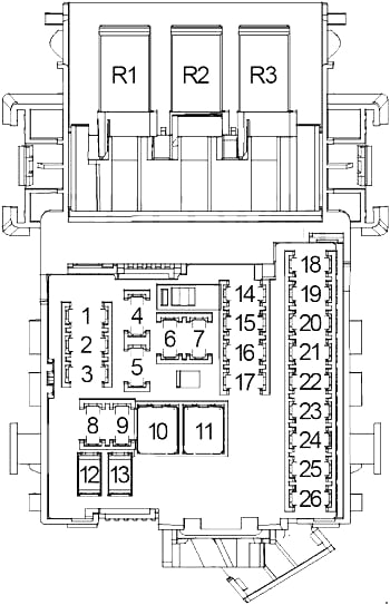
| Relay |
| R1 |
Air Conditioning Compressor Clutch |
| R2 |
Starter (No.1) |
| R3 |
– |
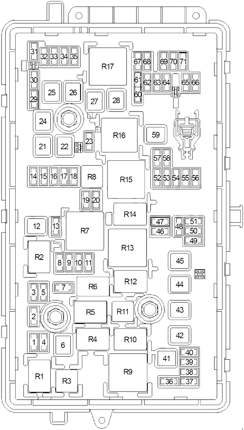
| R4 |
Front Wiper (Speed) |
| R5 |
Front Wiper (On/Off) |
| R6 |
2.4L LUK: Auxiliary Heater Coolant Pump |
| R7 |
Engine Control Module (ECM) |
| R8 |
2.5L LKW: Transmission Auxiliary Oil Pump |
| R9 |
Cooling Fan (No.2) |
| R10 |
Cooling Fan (No.3) |
| R11 |
2.5L LKW: Starter (No.2) |
| 2.4L LUK: Transmission Auxiliary Oil Pump |
| R12 |
– |
| R13 |
Cooling Fan (No.1) |
| R14 |
Low Beam |
| R15 |
Run/Crank |
| R16 |
2.4L LUK: Secondary Air Injection Pump |
| R17 |
Rear Window Defogger |
| Relay (Non-Serviceable) |
| R18 |
Child Security Lock Disable |
| R19 |
2.4L LUK: Starter/Generator Coolant Pump |
| R20 |
Headlamp (High Beam) |
| R21 |
Horn |
| R22 |
Front Fog Lamp |
| R23 |
Windshield Washer Pump |
| R24 |
2.4L LUK, 2.5 LKW: Secondary Air Injection Pump |
| R25 |
– |
| R26 |
– |