Chevrolet Silverado (2023) – fuse box diagram
Year of production: 2023
Engine Compartment Fuse Block
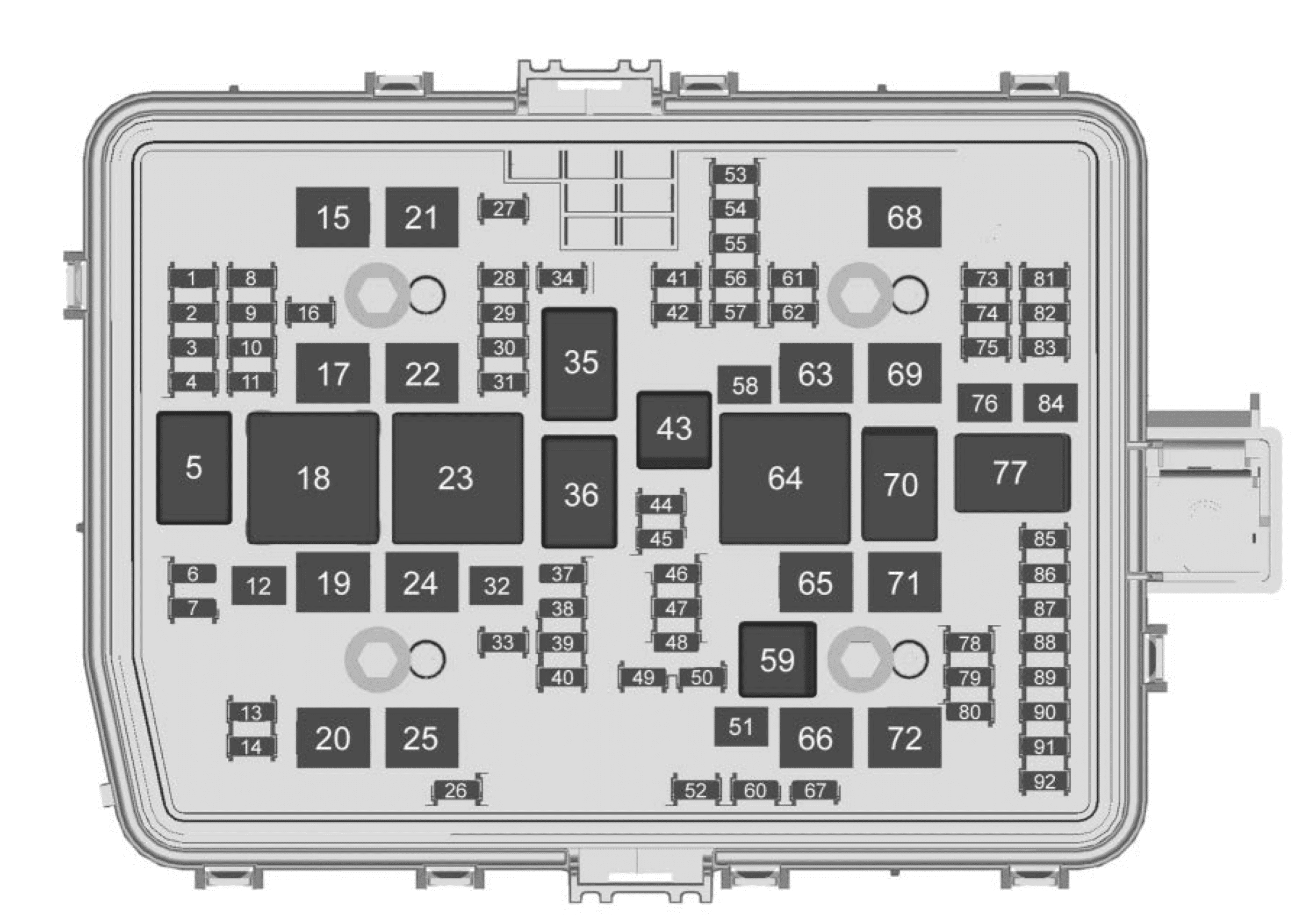
| Fuses | Usage |
| 1 | — |
| 2 | — |
| 3 | Headlamp Left |
| 4 | Headlamp Right |
| 6 | Exterior Lighting Module 7 |
| 7 | Exterior Lighting Module 4 |
| 8 | — |
| 9 | Exterior Lighting Module 5 |
| 10 | Exterior Lighting Module 6 |
| 11 | Body Control Module 2 |
| 12 | Rear Defog |
| 13 | Washer Front |
| 14 | — |
| 15 | — |
| 16 | — |
| 17 | IECL 1 |
| 19 | DC/AC Inverter |
| 20 | IECR 2 |
| 21 | — |
| 22 | IECL 2 |
| 24 | Fuel Heater |
| 25 | EVCM – Electronic Brake Control Module |
| 26 | — |
| 27 | Horn |
| 28 | Park Lamp Mirror/Grill |
| 29 | — |
| 30 | Exterior Lighting Module 3 |
| 31 | Exterior Lighting Module 1 |
| 32 | — |
| 33 | NOT R/C |
| 34 | Radars |
| 37 | MISC IP Headline Ignition |
| 38 | Seat Fan Ignition |
| 39 | — |
| 40 | MISC Body Ignition |
| 41 | Trailer Parking Lamp |
| 42 | — |
| 44 | Trailer Integration Module/ DEFC/ ICCM Ignition |
| 45 | Secondary Axle Motor |
| 46 | Engine Control Module/ Transmission Control Module/ Integrated Chassis Control Ignition |
| 47 | — |
| 48 | — |
| 49 | Transmission Auxiliary Oil Pump |
| 50 | A/C Pump |
| 51 | Transfer Case Control Module |
| 52 | Front Wiper |
| 53 | Center High Mounted Stoplamp |
| 54 | — |
| 55 | Trailer Back-up Lamp |
| 56 | SADS – Semi Active Damping System |
| 57 | TTPM/SBZA – Side Blind Zone Alert |
| 58 | Start Motor |
| 60 | PWR/TRN Sensor 2 |
| 61 | — |
| 62 | DEFC Battery 1/ Canister Vent Solenoid |
| 63 | Trailer Brake Control Module |
| 65 | — |
| 66 | Cooling Fan Motor Left |
| 67 | — |
| 68 | DEFC Battery 2 |
| 69 | Starter Pioion |
| 71 | Cooling Fan |
| 72 | Cooling Fan Right/Lower |
| 73 | Trailer Stop/Turn Left Lamp |
| 74 | Trailer Interface Module 2 |
| 75 | Integrated Chassis Control Module |
| 76 | Electric Running Board |
| 78 | Engine Control Module |
| 79 | Cabin Cool Pump |
| 80 | Powertrain Sensor 1 |
| 81 | Trailer Stop/Turn Lamp Right |
| 82 | Trailer Interface Module 1 |
| 83 | FTZM – Fuel Tank Zone Module |
| 84 | Trailer Battery |
| 85 | — |
| 86 | Engine Control Module |
| 87 | Injector B Even |
| 88 | O2 B Sensor |
| 89 | O2 A Sensor |
| 90 | Injector A odd |
| 91 | — |
| 92 | Aeroshutter |
| Relays | Usage |
| 5 | Rear Defog |
| 18 | DC/AC Inverter |
| 23 | Fuel Heater |
| 35 | Park Lamp/Front Grille Lamp |
| 36 | Run/Crank |
| 43 | Secondary Axle Motor |
| 59 | A/C Clutch |
| 64 | Starter Motor |
| 70 | Starter Motor |
| 77 | Powertrain |
Instrument Panel Fuse Block (left side)
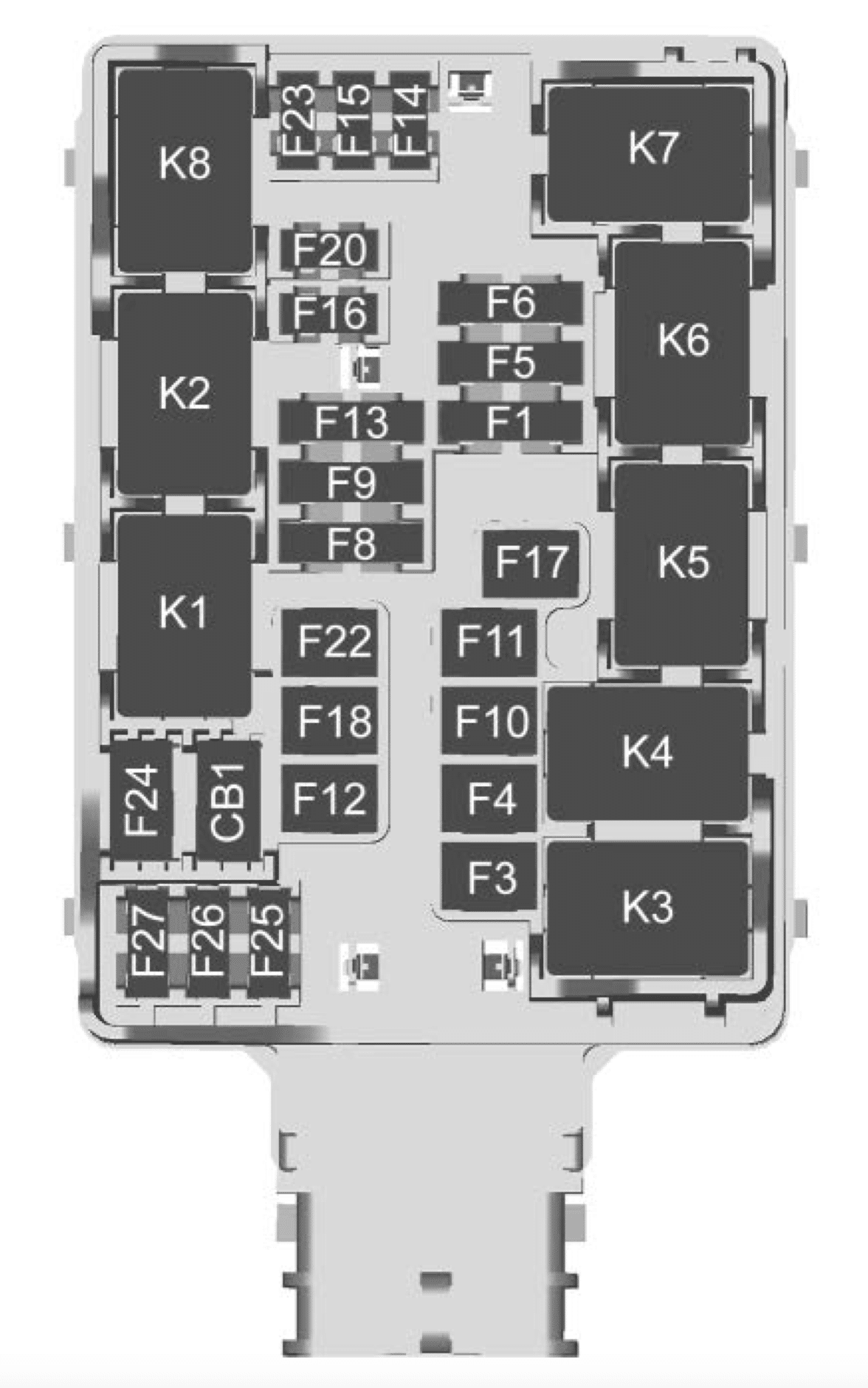
| Number | Usage |
| F1 | Rear heated seats left/right |
| F3 | — |
| F4 | — |
| F5 | Spare |
| F6 | Heated and Ventilated Seats Left/Right |
| F8 | — |
| F9 | EOCM – End Object Control Module/ Park Assist |
| F10 | — |
| F11 | — |
| F12 | Passenger power seat |
| F13 | — |
| F14 | Data Link Connector |
| F15 | — |
| F16 | AMP |
| F17 | MFEG – Multifunction Endgate Control |
| F18 | — |
| F20 | Endgate |
| F22 | Rear sliding window |
| F23 | Driver and Passenger Memory Seat Module |
| F24 | — |
| F25 | — |
| F26 | — |
| F27 | — |
| Circuit Breakers | |
| CB1 | — |
| Relays | |
| K1 | Rear sliding window open |
| K2 | Rear sliding window close |
| K3 | MFEG – Multifunction Endgate Control High |
| K4 | |
| K5 | MFEG – Multifunction Endgate Control High |
| K6 | MFEG – Multifunction Endgate Control High |
| K7 | — |
| K8 | — |
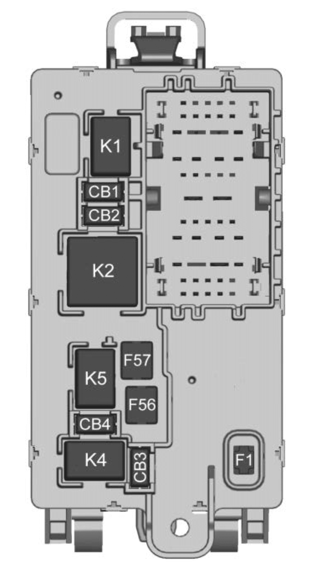
Instrument Panel Fuse Block (Right)
The right instrument panel fuse block access door is on the passenger side edge of the instrument panel.
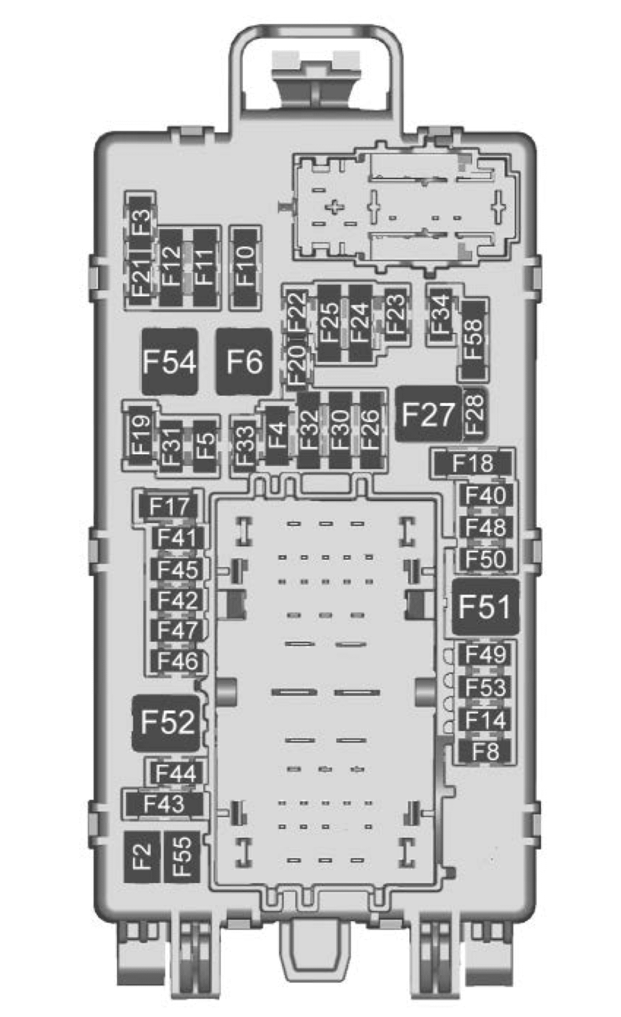
| Number | Usage |
| F1 | Right doors |
| F2 | Left doors |
| F3 | — |
| F4 | ELM – Exterior Lighting Module 2 |
| F5 | High Definition localization Module/ Instrument Panel Cluster/ Heads-up Display/ Humidity/ Integrated Center Stack |
| F6 | Front blower |
| F8 | Left Front Window Switch |
| F10 | Steering Tilt (LD)/ Upfitter Vehicle Module (HD) |
| F11 | Video Processing Module/ Overhead Control Camera |
| F12 | Central Gateway Module/ Telematics Control Platform/ Column Lock/ Driver Monitor System |
| F14 | |
| F17 | Steering wheel controls |
| F18 | — |
| F19 | — |
| F20 | — |
| F21 | — |
| F22 | Heated steering wheel |
| F23 | — |
| F24 | — |
| F25 | Spot Lamp Left/Right |
| F26 | USB ports/Special equipment option retained accessory power |
| F27 | Accessory power outlet/retained accessory power |
| F28 | Accessory power outlet/Battery |
| F30 | Sensing and diagnostic module/Automatic Occupant Sensing |
| F31 | Body control module 3 |
| F32 | Remote Function Actuator/ Wireless Charging Module/ Aux Jack/ Center Stack Module Aux Jack/ Trailer Brake Control Switch |
| F33 | Body control module 4 |
| F34 | — |
| F40 | — |
| F41 | — |
| F42 | Electric Park Brake Switch |
| F43 | — |
| F44 | Shifter Interface Board |
| F45 | Radio Low |
| F46 | — |
| F47 | — |
| F48 | Transmission control module |
| F49 | Body control module 1 |
| F50 | — |
| F51 | Battery 1 |
| F52 | Battery 2 |
| F53 | — |
| F54 | Sunroof |
| F55 | Driver power seat |
| F56 | DC/DC Converter Battery 1 |
| F57 | DC/DC Converter Battery 2 |
| F58 | — |
| Circuit Breakers | |
| CB1 | Accessory power outlet 2 |
| CB2 | — |
| CB3 | — |
| CB4 | — |
| Relays | |
| K1 | — |
| K2 | Retained accessory power/ Accessory 1 |
| K4 | — |
| K5 | — |
WARNING: Terminal and harness assignments for individual connectors will vary depending on vehicle equipment level, model, and market.